9
9 Connect the Power and Turn On the Router
Follow these steps to connect power to the Cisco 800 series router and turn it on.
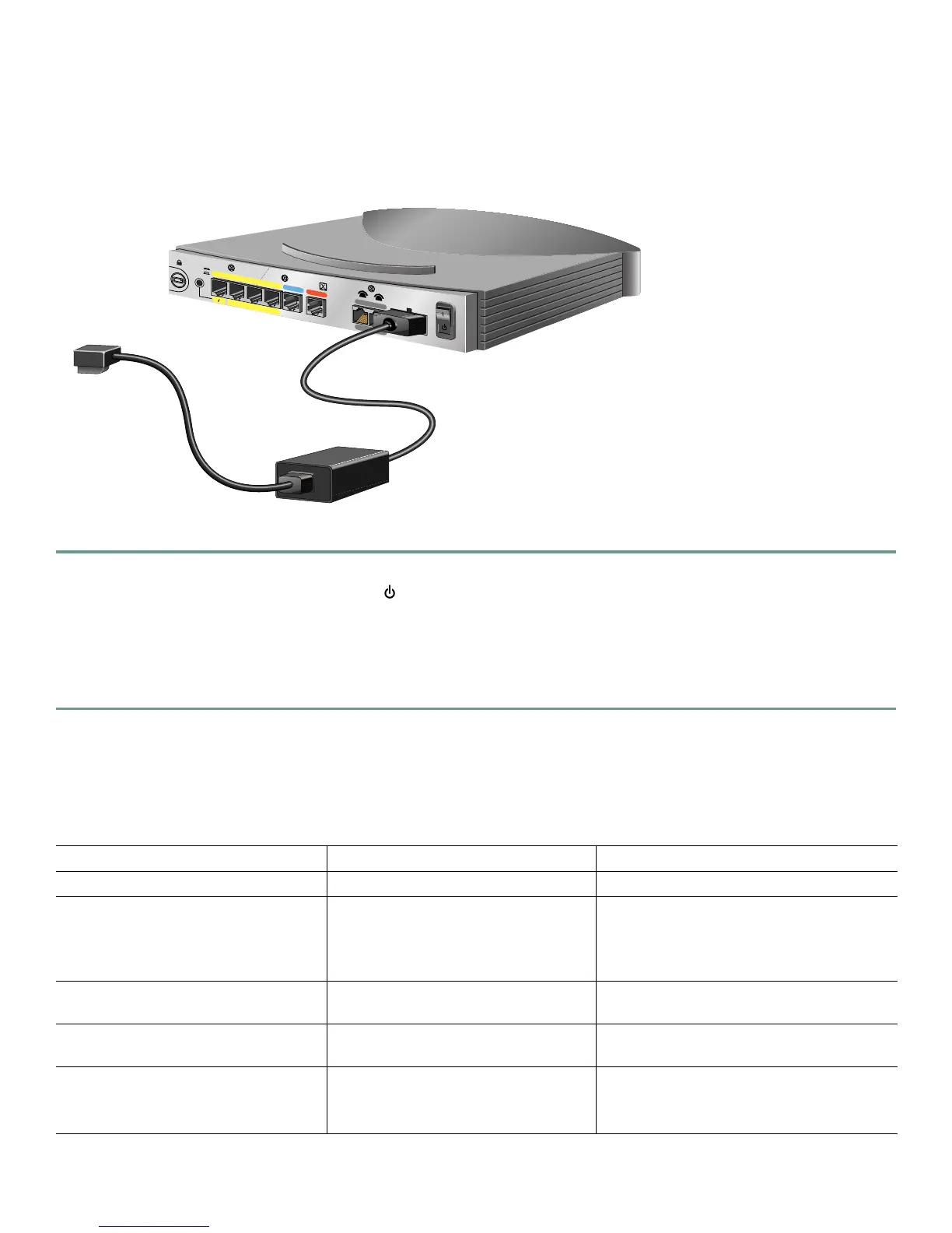
Figure 6 Connecting the Power to an 800 Series Router
Step 1 Make sure the router power is off.
Step 2 Set the power switch to the STANDBY ( ) position.
Step 3 Connect the power supply cable to the 8-pin connector on the router.
Step 4 Connect the power cord to the desktop power supply.
Step 5 Connect the other end of the power cord to an electrical outlet.
Step 6 Turn ON the router. Press the power switch to on (|).
10 Verifying the LEDs
Verify the power connection and all other connections (links) by checking the LEDs in the table below. If the LEDs are not on,
see the troubleshooting information in the Cisco 800 Series Routers Hardware Installation Guide.
Power/Link LEDs To Check Normal Patterns
Power OK On
To hub, server, PC, or workstation Cisco 801 or Cisco 802 back panel:
LINK LED
Cisco 803 or Cisco 804 front panel:
LKØ, LK1, LK2, and LK3 LEDs
On
To ISDN network using ISDN S/T port LINE, CH1, or CH2 On. CH1 or CH2 is on only when the router
has an active voice or data connection.
To ISDN network using ISDN U port NT1, LINE, CH1, or CH2 On.
CH1 or CH2 is on only when the router
has an active voice or data connection.
To telephone, fax, or modem PH1 or PH2
You can also pick up the handset and
listen for a dial tone.
On. PH1 or PH2 is on only when telephone,
fax, or modem is in use.
HUB
NO HUB
PHO
NE
Cisco 803
3
2
1
0
ETH
ERNET 10 BASE T
CON
SOLE
1
2
ISD
N S/T
Desktop power supply
To electrical outlet

 Loading...