Alarm Connection Guidelines
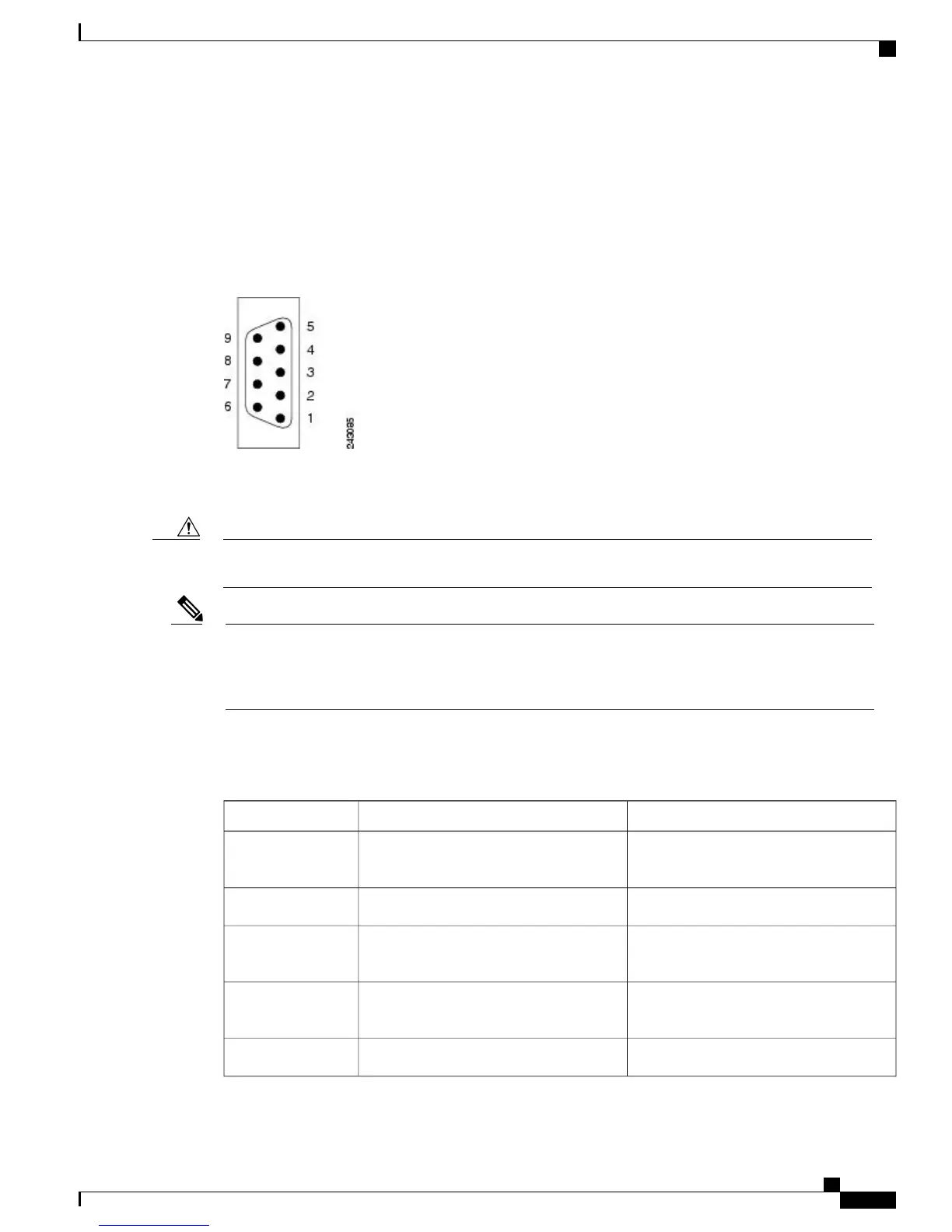
The RSP/RP card has an alarm connector on its front panel. This 9-pin D-subconnectors (ALARM OUT)
connects the router to an external site alarm maintenance system. When a critical, major, or minor alarm is
generated, it energizes the alarm relays on the RSP/RP card to activate the external site alarm.
Figure 64: Alarm Connector on the RSP/RP Card Front Panel
The alarm relay contacts on the RSP/RP card consist of standard common , normally open , and normally
closed relay contacts that are wired to the pins on the connectors.
Only safety extra-low voltage (SELV) circuits can be connected to the alarm connector. Maximum rating
for the alarm circuit is 100 mA, 50 V.
Caution
To comply with the intrabuilding lightning surge requirements of Telecordia GR-1089-CORE, Issue II,
Revision 01, February 1999, you must use a shielded cable when connecting to the external alarm port
on the RSP/RP card. The shielded cable is terminated by shielded connectors on both ends, with the cable
shield material tied to both connectors.
Note
This table lists the pin-to-signal correspondence between the cable connector pins and the alarm connector
relay contacts.
Table 8: Alarm Connector Pinout
NoteSignalPin
NC (normally closed) connected to CM
(common) when there is no Critical alarm
Critical alarm NC1
CommonCritical alarm CM2
NO (normally open) connected to CM
(common) during a Critical alarm
Critical alarm NO3
NC (normally closed) connected to CM
(common) when there is no Major alarm
Major alarm NC4
CommonMajor alarm CM5
Cisco ASR 9000 Series Aggregation Services Router Hardware Installation Guide
61
Preparing for Installation
RSP and RP Port Connection Guidelines
 Loading...


