2-18
Cisco Aironet 1000 Series Lightweight Access Point Hardware Installation Guide
OL-9403-04
Chapter 2 Installing the Access Point
Connecting the Ethernet and Power Cables
Note Some older switches and patch panels might not provide enough power to operate the access point. At
power-up, if the access point is unable to determine that the power source can supply sufficient power,
the access point automatically deactivates both radios to prevent an over-current condition. All access
LEDs are off.
Connecting to an Ethernet Network with an Inline Power Source
Note If your access point is connected to in-line power, do not connect the power module to the access point.
Follow these steps to connect the access point to the Ethernet LAN when you have an inline power
source:
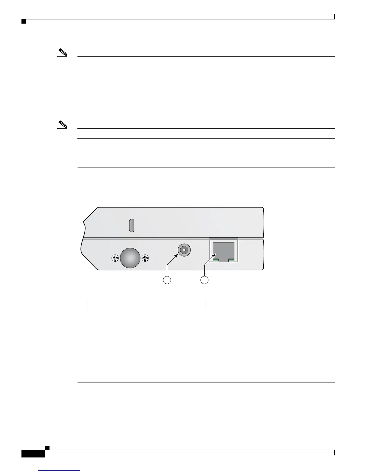
Step 1 Connect a Category 5 Ethernet cable to the RJ-45 Ethernet connector labeled Ethernet on the access
point (see Figure 2-13).
Figure 2-13 Ethernet and Power Ports
Step 2
Connect the other end of the Ethernet cable to one of the following:
• A switch with inline power (see the “Connecting the Ethernet and Power Cables” section on
page 2-17).
• The Ethernet connector on the power injector (AIR-PWRINJ-1000AF) labeled J1 DATA & PWR.
Also connect a Category 5 Ethernet cable from the power injector Ethernet connector labeled
J2 DATA to a non-powered Ethernet port on your 10/100 Ethernet LAN.
Step 3 Repeat Steps 1 to 2 for each access point requiring in-line power.
1 Ethernet port 2 48 VDC power port
146974
24 GHz Left
48 v
250Ma
Ethernet
1 2
 Loading...