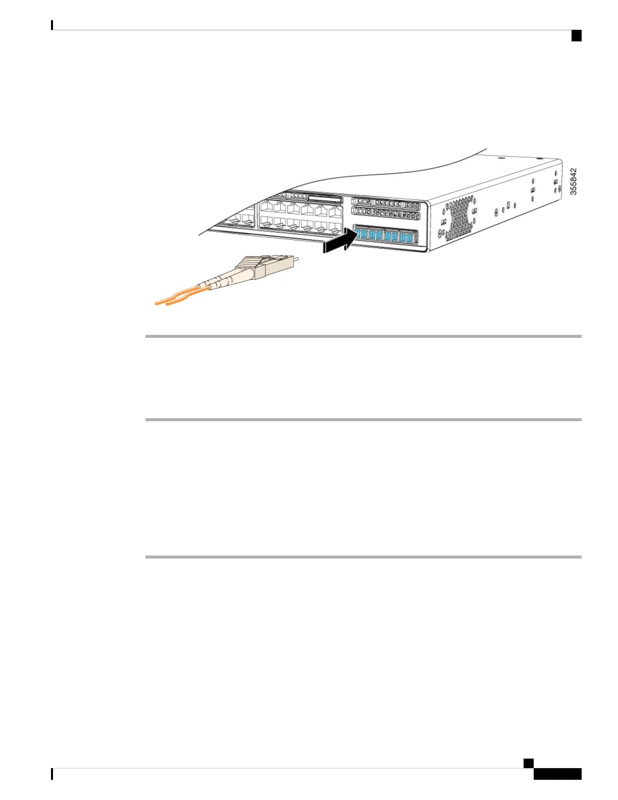
Figure 24: Installing an SFP/SFP+ Module in the Uplink Module Slot
Removing SFP/SFP+ Modules
Procedure
Step 1 Attach an ESD-preventive wrist strap to your wrist and to an earth ground surface.
Step 2 Disconnect the cable from the SFP/SFP+ module. For reattachment, note which cable connector plug is send
(TX) and which is receive (RX).
Step 3 Insert a dust plug into the optical ports of the SFP/SFP+ module to keep the optical interfaces clean.
Step 4 If the module has a bale-clasp latch, pull the bale out and down to eject the module. If you cannot use your
finger to open the latch, use a small, flat-blade screwdriver or other long, narrow instrument to open it.
Step 5 Grasp the SFP/SFP+ module, and carefully remove it from the slot.
Step 6 Place the SFP/SFP+ module in an antistatic bag or other protective environment.
Cisco Catalyst 9200 Series Switches Hardware Installation Guide
37
Installing a Network Module
Removing SFP/SFP+ Modules