Step 4 Press the release latch at the right side of the power supply module inward and slide the power supply out.
Do not leave the power-supply slot open for more than 90 seconds while the switch is operating.
Caution
This unit might have more than one power supply connection. All connections must be removed
to de-energize the unit. Statement 1028
Warning
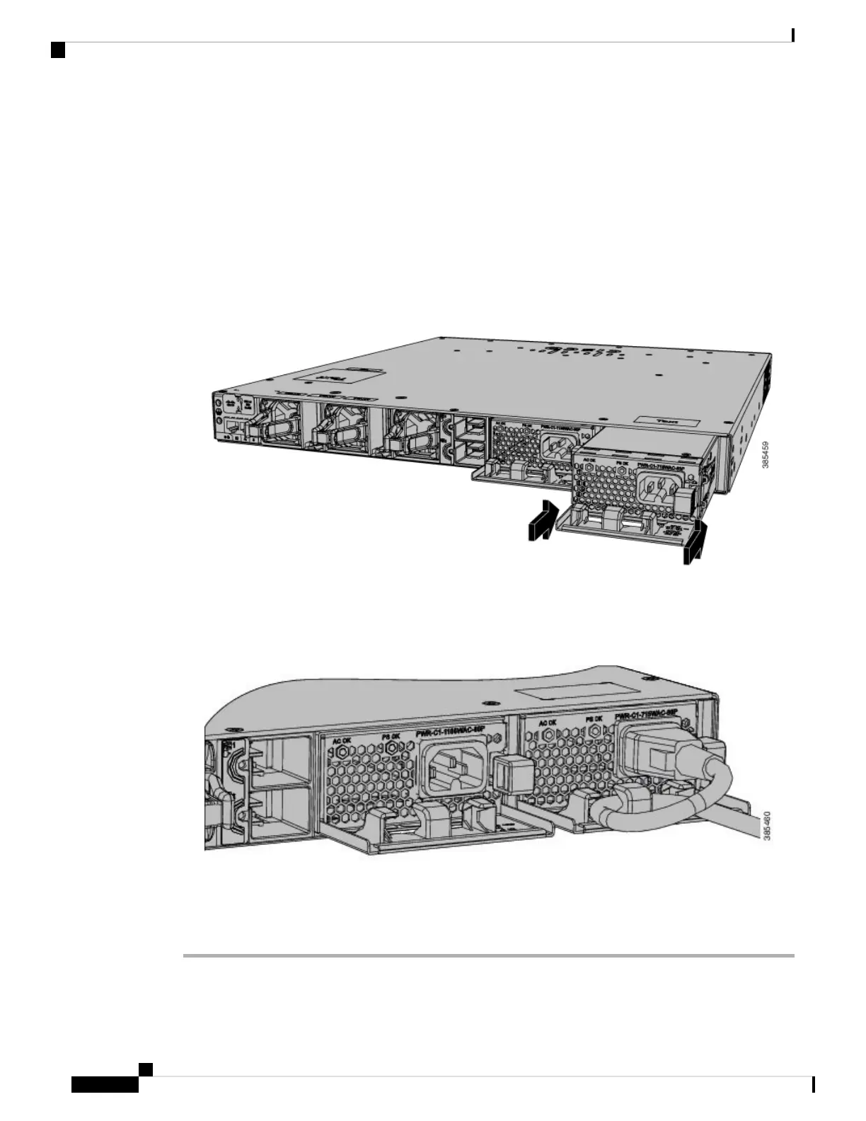
Step 5 Insert the new power supply into the power supply slot, and gently push it into the slot. When correctly inserted,
the 350 W and 715 W power supplies (excluding the power cord retainer) are flush with the switch rear panel.
The 1100 W power supply modules extend 1.5 inches and 1900 W power supply modules extend 1.5 inches
from the switch rear panel.
Figure 50: Inserting the AC Power Supply in the Switch
Step 6 (Optional) Make a loop in the power cord and thread it through the power cord retainer or use the cable-tie
retainer clip on the 1900 W supply.
Figure 51: AC-Power Supply with Power Cord Retainer
Step 7 Connect the power cord to the power supply and to an AC power outlet. Turn on the power at the power
source.
Step 8 Confirm that the power supply AC OK and PS OK LEDs are green.
Cisco Catalyst 9300 Series Switches Hardware Installation Guide
88
Installing a Power Supply
Installing or Replacing an AC Power Supply
 Loading...