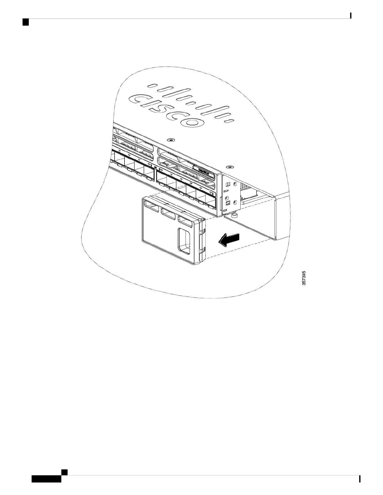
Figure 39: Removing the Blank Module
Verify the correct orientation of your module before installing it. Incorrect installation can damage
the module.
Caution
Do not install the network module with connected cables or installed pluggable transceivers.
Always remove any cables and transceiver modules before you install the network module.
Caution
A module interface might become error-disabled when a network module with connected
fiber-optic cables is installed or removed. If an interface is error-disabled, you can reenable the
interface by using the shutdown and no shutdown interface configuration commands.
Caution
Step 4 Position the module face up to install it in the module slot. Slide the module into the slot until the screw makes
contact with the chassis. Fasten the captive screws to secure the network module in place.
Figure 40: Installing the Network Module in the Switch
Step 5 Do one of the following:
Cisco Catalyst 9300 Series Switches Hardware Installation Guide
70
Installing a Network Module
Installing a Network Module