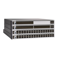
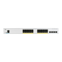
Installation Guidelines
When determining where to install the switch, verify that these guidelines are met:
• Clearance to the switch's front and rear panel should meet these conditions:
• Front-panel LEDs can be easily read.
• Access to ports is sufficient for unrestricted cabling.
• AC power cord can reach from the AC power outlet to the connector on the switch's rear panel.
• Cabling is away from sources of electrical noise, such as radios, power lines, and fluorescent lighting
fixtures. Make sure that the cabling is safely away from other devices that might damage the cables.
• Airflow around the switch and through the vents is unrestricted. To avoid any flow blockage, we strongly
recommend these guidelines:
• Allow at least 3 in. (7.6 cm) of clearance from the left and the right sides, and the front and rear of
the switch.
• Allow at least 1.75 in. (4 cm) of clearance from the top cover, if you are installing the switch in
upright position.
• Allow at least 3 in. (7.6 cm) of clearance from the top cover, if you are installing the switch.
• Temperature around the unit does not exceed 122°F (50°C). If the switch is installed in a closed or
multirack assembly, the temperature around it might be greater than normal room temperature.
• Humidity around the switch does not exceed 95 percent.
• Altitude at the installation site is not greater than 10,000 feet.
• For 10/100/1000 fixed ports, the cable length from a switch to a connected device cannot exceed 328
feet (100 meters).
• Cooling mechanisms, such as fans and blowers in the switch, can draw dust and other particles causing
contaminant build-up inside the chassis, which can result in system malfunction. You must install this
equipment in an environment as free from dust and foreign conductive material (such as metal flakes
from construction activities) as is possible.
• None of the switch models can be deployed outside of the wiring closet. These switches can only be
deployed indoors.
Verifying Switch Operation
Before you install the switch in a rack, on a wall, or on a table or shelf, power on the switch and verify that
it passes POST.
To power on the switch, plug one end of the AC power cord into the switch AC power connector, and plug
the other end into an AC power outlet.
As the switch powers on, it begins the POST, a series of tests that runs automatically to ensure that the switch
functions properly. LEDs can blink during the test. The SYST LED blinks green.
Cisco Catalyst 1000 Series 24-Port and 48-Port Switch Hardware Installation Guide
17
Switch Installation
Installation Guidelines
 Loading...