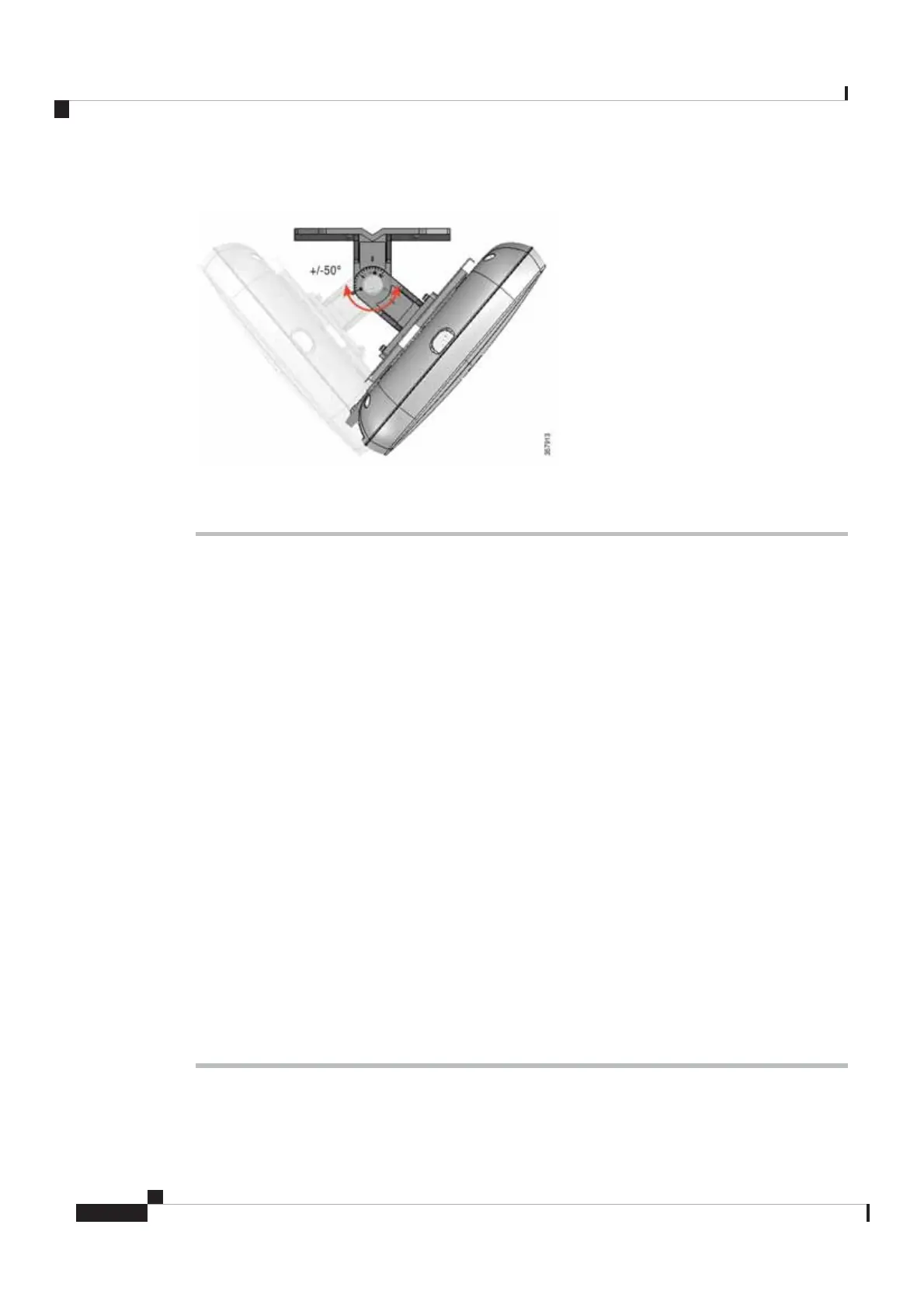
Figure 26: Single Axis Mount Pivot Adjustment
Procedure
Step 1 Determine the mounting location for the access point.
Step 2 Attach the wall mounting flange to the wall or ceiling using four M6 screws through the holes in the bracket.
The mounting surface, attaching screws, and wall anchors must support a 50 lb (22.7–kg) static
weight.
Caution
The mounting kit does not include the M6 screws for securing the bracket to the mounting surface.
Note
Step 3 Attach the AIR-AP-BRACKET-2 to the access point bracket using four M4 screws through the holes in the
bracket.
Hand tighten snug the four screws.
Step 4 Assemble the access point bracket to the wall mounting flange.
Hand tighten all screws and nuts. See Figure 23: Exploded View of the Single Axis Articulating Bracket
Hardware Assembly, on page 26
Step 5 Attach the access point to the AIR-AP-BRACKET-2.
Use a 13-mm wrench to loosen or tighten the fasteners.
Step 6 Adjust the access point's position.
Loosen the adjustment pivot nut slightly to allow for adjustment. Use the markings on the flange bracket as
a guide. You may adjust the angle ±50 degrees.
Step 7 After adjusting the access point position, tighten the pivot nut.
Tighten the nut at the pivot point to 5.6 to 5.9 lb-ft (7.6 to 8.0 Nm) torque.
Step 8 Connect the Ethernet cable to the access point using the termination kit.
Cisco Catalyst Wireless 9166D1 Series Wi-Fi 6E Access Point Hardware Installation Guide
28
Installation Overview
Mounting the Access Point Using Single Axis Articulating Bracket
 Loading...