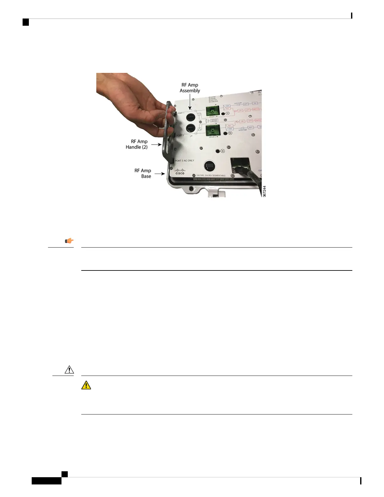
6. Grasp the two metal handles on the RF amplifier assembly and carefully lift the RF assembly out of the
housing.
7. To replace the RF amplifier assembly in the housing, carefully align the assembly in the housing, lower
it into place and push down to reconnect the rear panel connectors.
8. Secure the RF amplifier assembly to the housing with the seven cross-head shoulder screws.
Tighten the screws in order by number, 1 through 7. Repeat the sequence twice, ending with a torque of 18
to 20 in-lbs (2.0 to 2.25 Nm).
Important
9. Plug AC1/DC connector, forward path connector, reverse path connector and AC2 connector on the RF
amplifier assembly.
10. Reinstall the AC power shunts in their proper locations on the RF amp assembly.
11. Close the housing. See Opening and Closing the Housing, on page 1.
12. Perform the setup procedure in Setup and Operation to verify node performance.
Care and Cleaning of Optical Connectors
Proper operation of this equipment requires clean optical fibers. Dirty fibers will adversely affect performance.
Proper cleaning is imperative.
Caution
The proper procedure for cleaning optical connectors depends on the connector type. The following describes
general instructions for fiber-optic cleaning. Use your company's established procedures, if any, but also
consider the following.
Maintenance
10
Maintenance
Care and Cleaning of Optical Connectors
 Loading...


