5
Product Overview
Alarm Connector (PoE Models Only)
The switch can operate with a single power source or with dual power sources. When both power sources are
operational, the switch draws power from the DC source with the higher voltage. If one of the two power sources fail,
the other continues to power the switch.
Alarm Connector (PoE Models Only)
You connect the alarm signals to the switch through the alarm connector. The switch supports one alarm output relay.
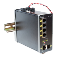
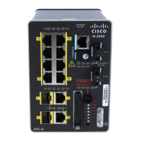
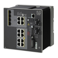
The alarm connector is on the top panel.
The alarm connector provides three alarm wire connections. The connector is attached to the switch top panel with the
provided captive screws.
The alarm output circuit is a relay with a normally open and a normally closed contact. The switch is configured to detect
faults that are used to energize the relay coil and change the state on both of the relay contacts: normally open contacts
close, and normally closed contacts open. The alarm output relay can be used to control an external alarm device, such
as a bell or a light.
For more information about the alarm connector, see Cable and Connectors, page 37
