4
Product Overview
Connectors
SFP Modules Supported
The SFP modules are switch Ethernet SFP modules that provide connections to other devices. Depending on the switch
model, these field-replaceable transceiver modules provide uplink or downlink interfaces. The modules have LC
connectors for fiber-optic connections. For a complete list of supported SFP modules refer to the Data Sheet.
Connectors
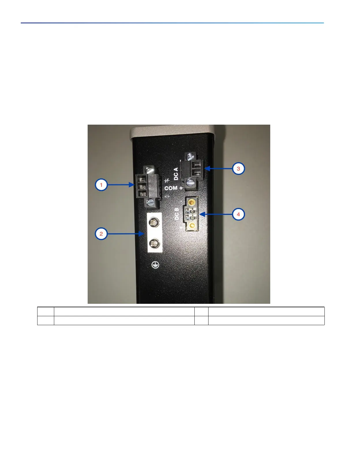
Figure 2 Cisco IE-1000-4P2S-LM top panel shown
DC Power Connector
You connect the DC power to the switch through the top panel connectors. The switch has a dual-feed DC power supply;
two connectors provide primary and secondary DC power (DC-A and DC-B). See Figure 1 on page 3. Each power
connector has an LED status indicator.
The switch power connectors are attached to the switch chassis. Each power connector has screw terminals for
terminating the DC power. All connectors are attached to the switch top panel with the provided captive screws.
The power connector labeling is on the panel. The positive DC power connection is labeled “+”, and the return
connection is labeled “–”.
1 Alarm connector (PoE Models Only) 3 Power connector DC-A
2 Protective ground connection 4 Power connector DC-B (PoE Models Only)
 Loading...