19
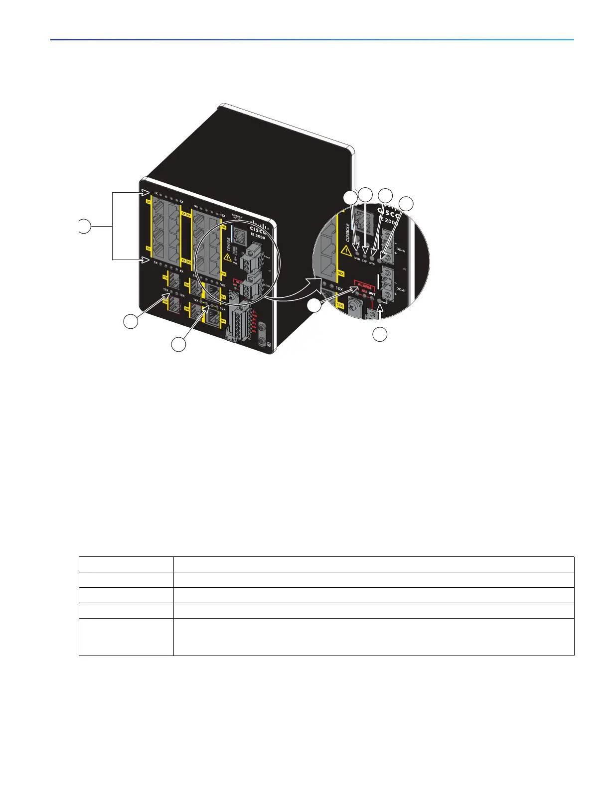
Figure 9 LEDs on the Cisco IE 2000 Switch
Note: On IE 2000 switches with PoE support, the two SFP ports and the associated LEDs are replaced by a PoE DC-input
terminal block and a PoE LED. For more information, see PoE Status LED, page 22.
Express Setup LED
The Express Setup LED displays the express setup mode for the initial configuration.
1 Alarm LEDs 6 Power connector DC-B LED
2 USB mini-Type B (console) port LED 7 10/100BASE-T downlink port LEDs
3 Express Setup LED 8 SFP module slot LEDs
4 System LED 9 Dual-purpose uplink port LEDs
5 Power connector DC-A LED
Table 3 Express Setup LED
Color Setup Status
Off (dark) Switch is configured as a managed switch.
Solid green Switch is operating normally.
Blinking green Switch is in initial setup, in recovery, or initial setup is incomplete.
Solid red Switch failed to start initial setup or recovery because there is no available switch port to which
to connect the management station. Disconnect a device from a switch port, and then press
the Express Setup button.
 Loading...