3
Chapter 2: Product Overview
24-Port 10/100 + 2-Port Gigabit Switch + 2 MiniGBIC
Chapter 2:
Product Overview
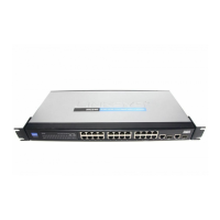
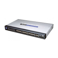
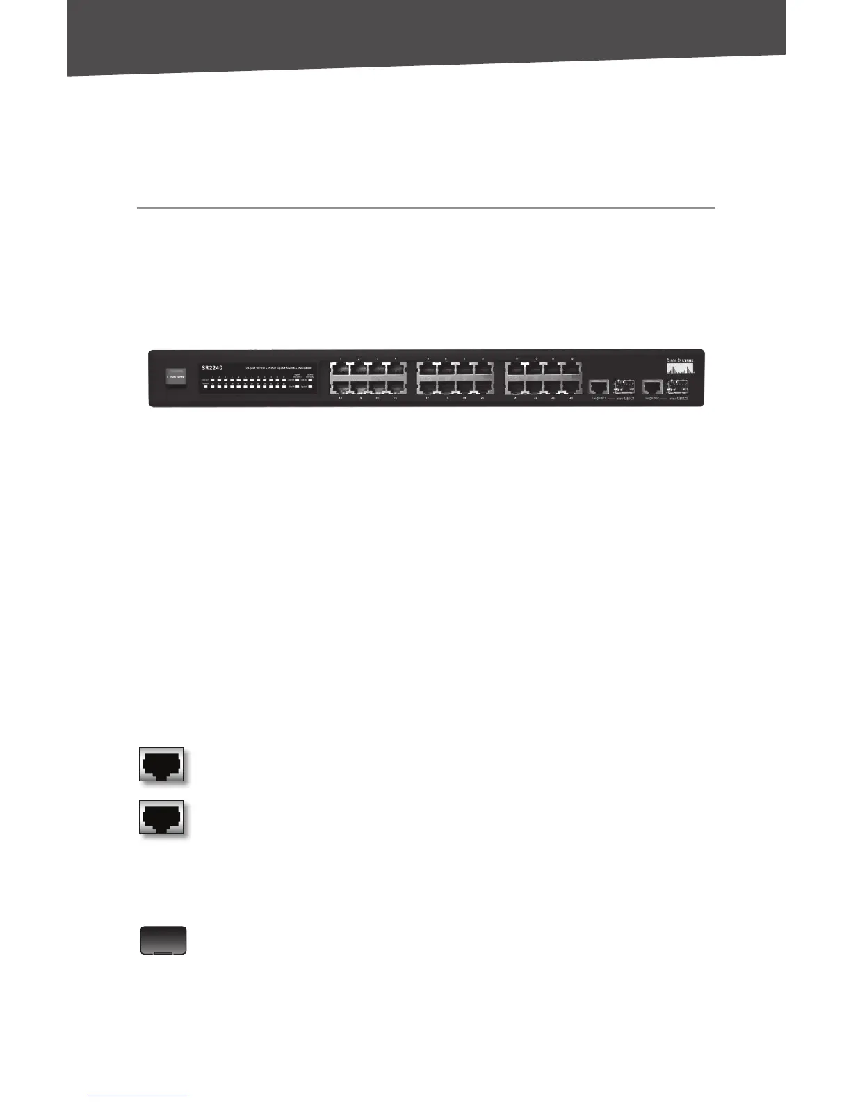
Front Panel
The LEDs and network ports are located on the front panel of the
Switch.
Front Panel
LEDs
System (Green) This LED lights up and remains lit when the Switch is
powered on.
1-24
(Green) Each LED lights up when a connection is made through its
corresponding port. It flashes when the corresponding port is active.
Gigabit/miniGBIC 1-2
(Green) The Gigabit/miniGBIC LED lights up
when a connection is made through the corresponding Gigabit port. It
flashes when the corresponding port is active.
Ports
1-24 These ports connect the Switch to network devices,
such as computers.
Gigabit 1-2 The Gigabit RJ-45 ports support 10/100/1000
Mbps connections and are connection points for network
devices such as Gigabit servers. Each Gigabit RJ-45 port is
paired with a miniGBIC port. If a miniGBIC module is present,
the corresponding 10/100/1000 RJ-45 port will be disabled.
MiniGBIC 1-2 The two miniGBIC (Gigabit interface converter)
ports are connection points for miniGBIC modules, so the
Switch can uplink via fiber to another switch or two. The
miniGBIC ports are compatible with the MGBSX1, MGBLH1,
and MGBT1 only.
 Loading...