Send document comments to ucs-docfeedback@cisco.com
14
Cisco UCS B200 Blade Server Installation and Service Note
OL-22473-02
Removing a Blade Server Cover
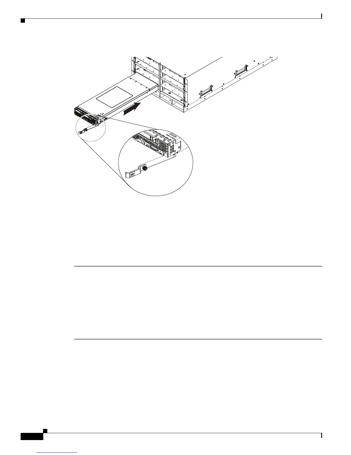
Figure 5 Positioning a Blade Server in the Chassis
Step 2 Open the ejector lever in the front of the blade server.
Step 3 Gently slide the blade into the opening until you cannot push it any farther.
Step 4 Press the ejector lever so that it catches the edge of the chassis and presses the blade server all the way in.
Step 5 Tighten the captive screw on the front of the blade to no more than 3 in-lbs. Tightening with bare fingers
only is unlikely to lead to stripped or damaged captive screws.
Step 6 Power on the server. UCS Manager will automatically re acknowledge, reassociate, and recommission
the server, provided any hardware changes are allowed by the service profile.
Figure 5 shows the positioning of a blade server in the chassis. Blade servers reside within the eight
upper slots of the chassis.
Removing a Blade Server Cover
Replacing the cover is the reverse of removing the cover. To open a blade server:
Step 1 Press and hold the button down as shown in Figure 6
Step 2 While holding the back end of the cover, pull the cover up and back.
 Loading...