3-32
Cisco UCS C200 Server Installation and Service Guide
OL-20732-02
Chapter 3 Maintaining the Server
Installing or Replacing Components
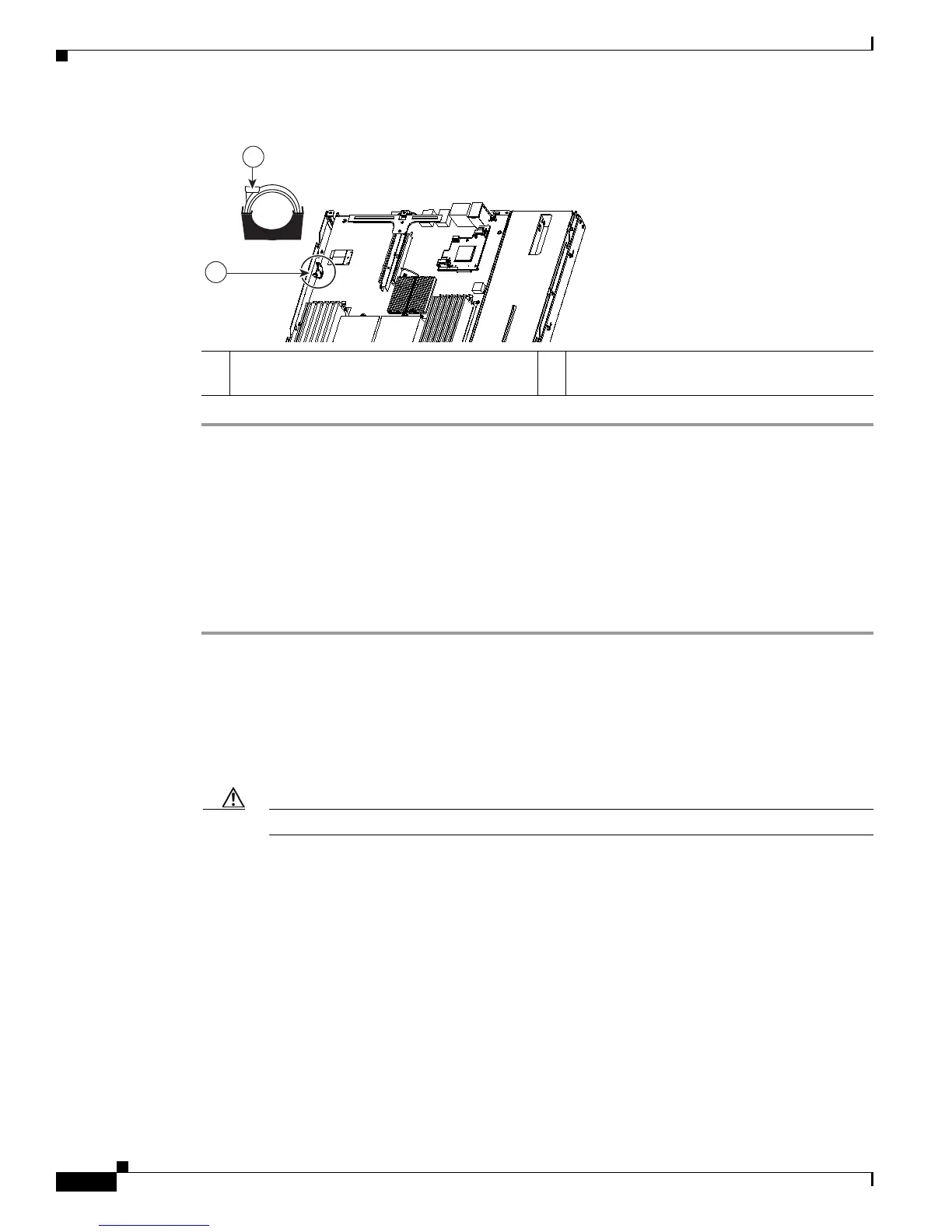
Figure 3-19 Removing and Replacing a Motherboard CMOS Battery
Installing a Trusted Platform Module
The qualified and supported part numbers for this component are subject to change over time. For the most
up-to-date list of replaceable components, see the following URL and then scroll to Technical Specifications:
http://www.cisco.com/en/US/products/ps10493/products_data_sheets_list.html
To install or replace a trusted platform module (TPM), follow these steps:
Step 1 Remove a TPM:
a. Power off the server as described in the “Shutting Down and Powering Off the Server” section on
page 3-7.
b. Disconnect all power cords from the power supplies.
c. Slide the server out the front of the rack far enough so that you can remove the top cover. You might
have to detach cables from the rear panel to provide clearance.
Caution If you cannot safely view and access the component, remove the server from the rack.
d. Remove the top cover as described in the “Removing and Replacing the Server Top Cover” section
on page 3-9.
e. Remove the PCIe riser card assembly to provide clearance to the TPM.
See the “Replacing a PCIe Riser Card Assembly” section on page 3-34 for instructions.
f. Remove the securing screw that holds the TPM to the motherboard standoff (see Figure 3-20).
g. Lift up on both ends of the TPM to free it from the socket on the motherboard.
Step 2 Install a TPM:
a. Align the connector that is on the underside of the new TPM with motherboard socket JP2, and then
press firmly on both ends of the TPM to press the connector into the socket.
b. Replace the securing screw that holds the TPM to the motherboard standoff.
c. Replace the PCIe riser card assembly.
1 Motherboard CMOS battery socket
(positive side toward chassis wall)
2 Battery retaining clip
 Loading...