3-2
Cisco UCS C22 Server Installation and Service Guide
OL-26646-01
Chapter 3 Maintaining the Server
Status LEDs and Buttons
Status LEDs and Buttons
This section describes the location and meaning of LEDs and buttons and includes the following topics:
• Front Panel LEDs, page 3-2
• Rear Panel LEDs and Buttons, page 3-4
Front Panel LEDs
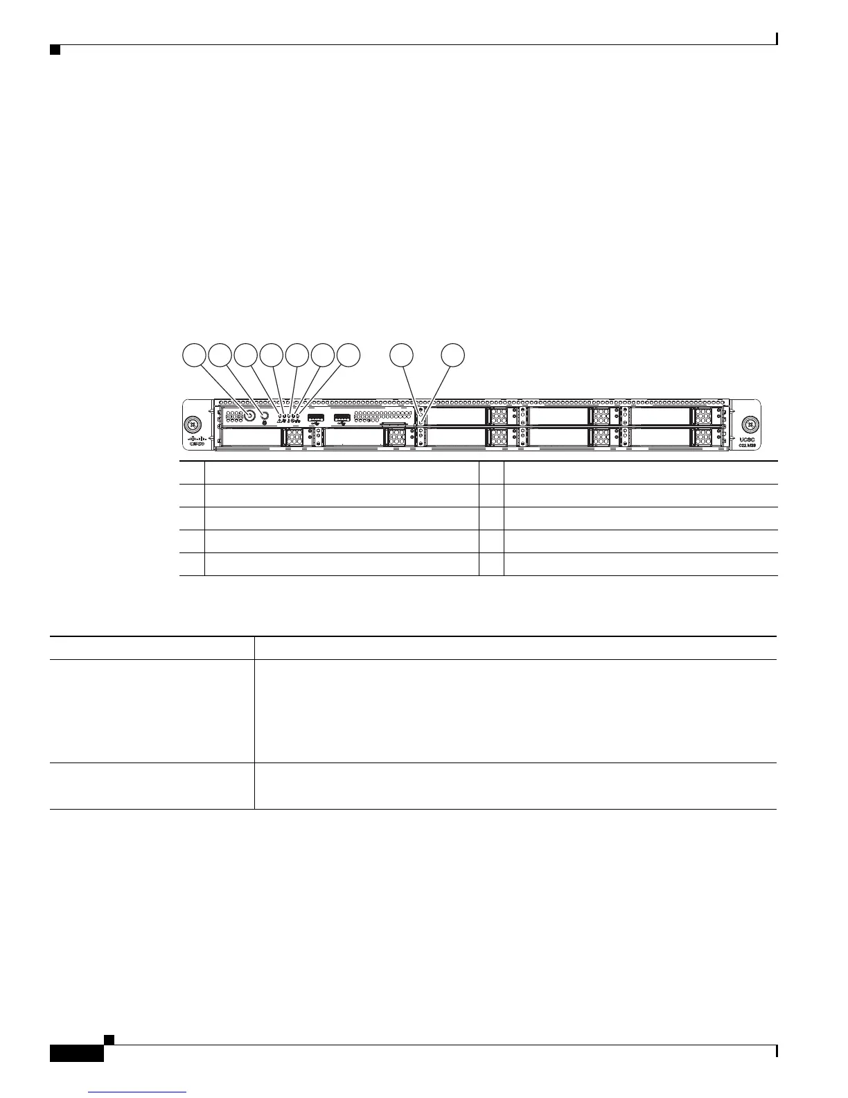
Figure 3-1 shows the front panel LEDs. Table 3-1 defines the LED states.
Figure 3-1 Front Panel LEDs
1 Power button/Power status LED 6 Power supply status LED
2 Identification button/LED 7 Network link activity LED
3 System status LED 8 Hard drive fault LED
4 Fan status LED 9 Hard drive activity LED
5 Temperature status LED –
Ta b l e 3-1 Front Panel LEDs, Definitions of States
LED Name State
Power button/Power status LED • Off—There is no AC power to the server.
• Amber—The server is in standby power mode. Power is supplied only to the CIMC
and some motherboard functions.
• Green—The server is in main power mode. Power is supplied to all server
components.
Identification • Off—The Identification LED is not in use.
• Blue—The Identification LED is activated.
HDD06
HDD01
HDD07
HDD02
HDD08
HDD03
HDD04
HDD04 HDD05
HDD05
1 2 3 4 5 6 7 8 9
333247
 Loading...