3-12
Cisco UCS C22 Server Installation and Service Guide
OL-26646-01
Chapter 3 Maintaining the Server
Installing or Replacing Server Components
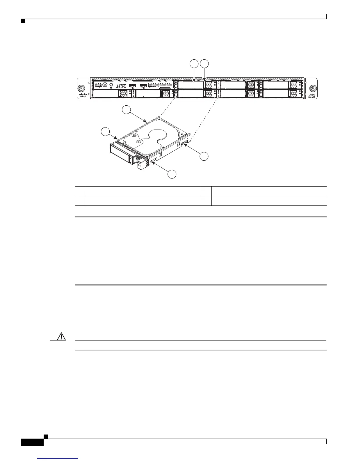
Figure 3-6 Replacing Hard Drives
Replacing a Front Operations Panel Board
The front operations panel board contains the front panel LEDs, Power and Identification buttons, and
the front USB ports.
To replace a front operations panel board, follow these steps:
Step 1 Remove the front operations panel board that you are replacing. See Figure 3-8:
a. Power off the server as described in the “Shutting Down and Powering Off the Server” section on
page 3-6.
b. Slide the server out the front of the rack far enough so that you can remove the top cover. You might
have to detach cables from the rear panel to provide clearance.
Caution If you cannot safely view and access the component, remove the server from the rack.
c. Remove the top cover as described in “Removing and Replacing the Server Top Cover” section on
page 3-7.
d. Remove the front chassis panel as described in Removing and Replacing the Front Chassis Panel,
page 3-8.
e. Disconnect the two ribbon cables from the front operations panel board.
To disconnect the ribbon cables, open their hinged connectors.
f. Use a #2 Phillips-head screwdriver to remove the two screws that secure the board to the chassis.
1 Ejector lever 3 Drive tray securing screws (4)
2 Release button –
285205
HDD06
HDD01
HDD07
HDD02
HDD08
HDD03
HDD04HDD04HDD04 HDD05HDD05HDD05
3
3
3
3
1 2
 Loading...