10
Caution Do not place anything that weighs more than 5 pounds (2.25 kg) on top of the chassis. Do not stack chassis on a
desktop. Excessive distributed weight of more than 5 pounds or a pound point load of 5 pounds on top can damage
the chassis.
After you install the chassis, connect it to a reliable earth ground. For the chassis ground connection procedures, see the
“Grounding the Chassis” section on page 12.
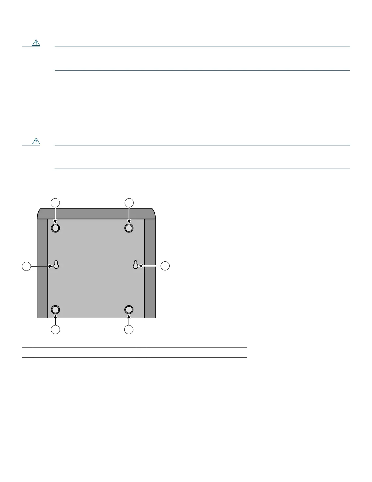
Mounting the Chassis onto a Wall
You can mount the voice gateway chassis onto a wall or other vertical surface by using the molded mounting brackets on the
bottom of the chassis and two number-six, 3/4-inch (M3.5 x 20 mm) screws. You must provide the screws. Figure 6 shows the
mounting-screw slots on the chassis.
Caution If you are mounting the chassis onto drywall, use two hollow-wall anchors (1/8 inch with 5/16-inch drill bit, or M3
with 8-mm drill bit) to secure the screws. If the screws are not properly anchored, the strain of the network cable
connections could pull the chassis from the wall.
Figure 6 Mounting-Screw Slots for Wall-Mounting the Cisco VG202, Cisco VG202XM, Cisco VG204, or Cisco VG204XM Voice
Gateway Chassis
Before You Begin
Ensure that you meet the following conditions when you mount the chassis onto a wall:
• The LEDs on the front panel face upward and are easily visible, because you will use the LEDs as status and problem
indicators.
• The back panel faces downward, to reduce strain on the cable connections.
• The power supply rests on a horizontal surface such as the floor or a table. If the power supply is not supported, it can place
strain on the power supply cable and cause it to disconnect from the connector on the back panel of the chassis.
1
Rubber feet
2
Mounting-screw slots
 Loading...