12
Grounding the Chassis
You must connect the voice gateway chassis to a reliable earth ground; the ground wire must be installed in accordance with
local electrical safety standards.
• For NEC-compliant grounding, use size AWG 14 (2 mm
2
) or larger wire and an appropriate user-supplied ring terminal.
• For EN/IEC 60950-compliant grounding, use size AWG 18 (1 mm
2
) or larger wire and an appropriate user-supplied ring
terminal.
• To ground the chassis, you will need a crimp tool and a number 2 Phillips screwdriver.
Before You Begin
Locate a suitable ground.
Tip Using a multimeter, measure the resistance between various possible ground locations, such as between the ground of
a junction box (outlet) and the ground of a power tap, between the ground of a junction box and a metal water pipe,
between the voice gateway chassis and the ground of a power tap, or between the chassis and the ground of a junction
box. A good ground connection should read between 0.0 and 0.5 Ohm.
Procedure
Step 1 Strip one end of the ground wire to the length required for the ring terminal.
Step 2 Crimp the ground wire to the ring terminal, using a crimp tool of the appropriate size.
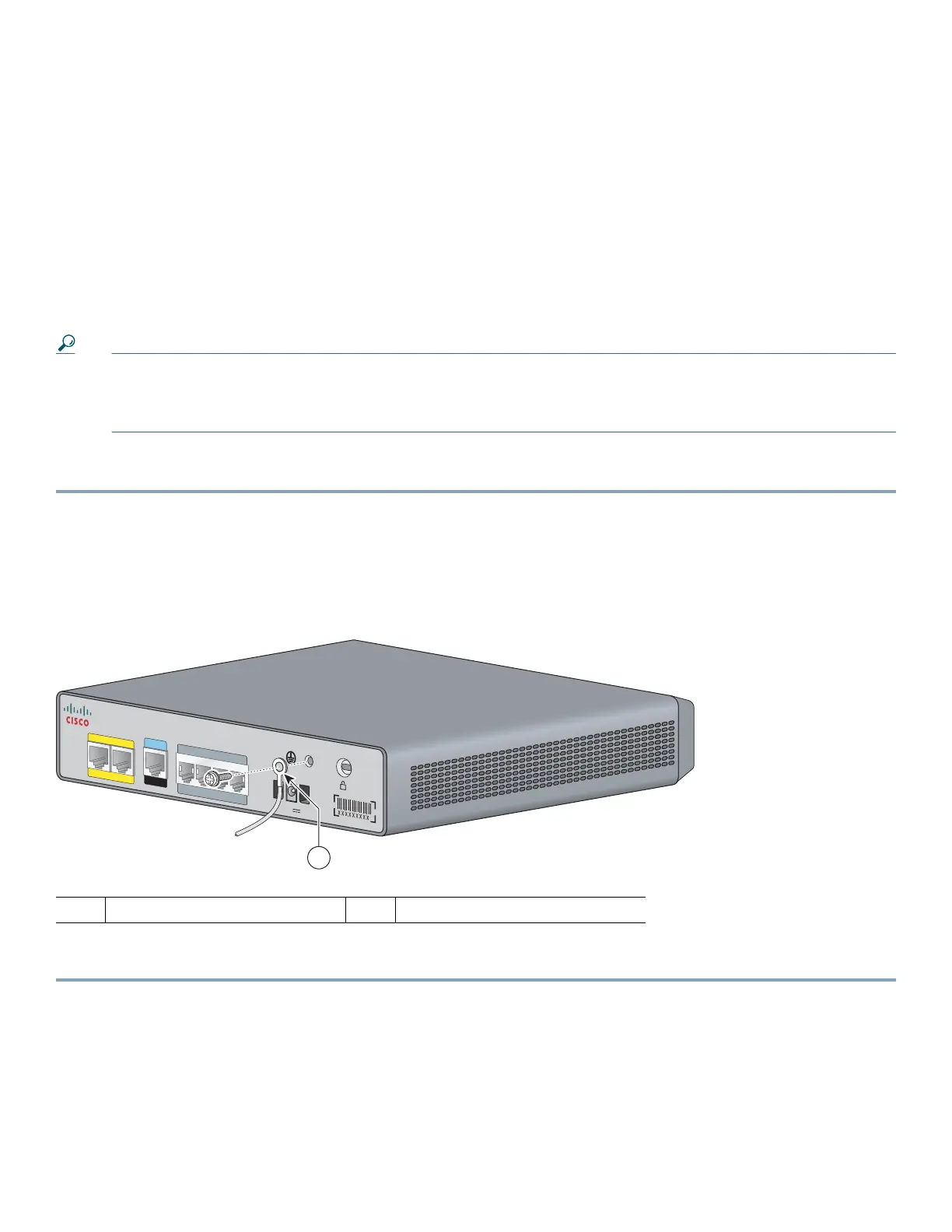
Step 3 Attach the ring terminal to the chassis as shown in Figure 8. For a ring terminal, use one of the screws provided. Use a
number 2 Phillips screwdriver, and tighten the screws to a torque of 8 to 10 in-lb (0.9 to 1.1 N-m).
Figure 8 Chassis Ground Connection Using Ring Terminal
Step 4 Connect the other end of the ground wire to a grounding point at your site.
1 Ring terminal attachment
232069
VG204
12V
DC SA
CONSOLE
AUX
Fas tEthernet
0/1
0/0
FXS
0/1
0/20/3
0/0
1
 Loading...