DANGER
DANGER
WARNING
WARNING
CAUTION
CAUTION
Product-specic cautions: Flow sensor for compressed air PF-F/PFU series
Pneumatic components (sensors)
Safety Precautions
Be sure to read this section before use.
Refer to Intro Page 63 for general precautions regarding pneumatic components
and refer to " Safety precautions" for detailed precautions for individual series.
Design/selection
1. Checking the specications
■
Never use with a ammable uid.
■
Use the product in the range of conditions specied
for the product.
The product in this catalog is designed for use only in a compressed
air system. Use with pressures or temperatures outside the
specications range may result in damage or operation failure.
■
This product cannot be used as a billing meter.
Do not use this product for commercial transactions
as it is not compliant with the Measurement Act.
Intended applications include industrial sensors.
■
Because compressed air or nitrogen gas is used as
an applicable uid, do not use uids other than
these, because accuracy cannot be guaranteed.
2. Safety design
■
Take measures to prevent physical harm or property
damage in the event of failure of this product
.
■
Understand the characteristics of compressed air
before designing a pneumatic circuit.
●
Pop-out, air discharge, or leakage due to air compression
and expansion may occur.
●
Design the circuit so that compressed air in the system is
exhausted.
■
Check for leakage current to avoid malfunction
caused by the leakage current.
●
When using a programmable controller, leakage current
may cause malfunction.
■
Although there is no movable section in the ow
rate sensor, when repeating ON/OFF of the
solenoid valve, the mesh section or xed section of
the rectier may move slightly and this may result
in the generation of particles. When the generation
of particles must be eliminated, be sure to install a
lter on the secondary side (downstream side) of
the ow rate sensor.
■
Exerts no inuence on performance as it uses
compressed air and a small amount of leakage is
tolerable. Contact CKD if no leakage is required.
■
The monitor of the display separated PFD Series
cannot be connected to PF-F/PFU Series. When
making the connection, this product could break.
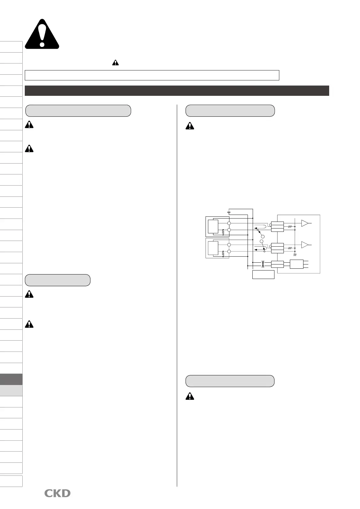
■
Precautions for analog output "A1"
Connecting multiple analog output 4 to 20 mA sensors
to the same common input circuit (host computer, PLC,
etc.) as shown above causes interference between the
signals, preventing correct operation. In this case, use
the voltage output (standard, A2, A3).
* The voltage at point A and that at point B are
connected inside the input circuit, which gives
them the same electrical potential, creating an
error in the respective analog outputs.
If the power supply (24 VDC) of the host input circuit is not isolated,
install separate power supplies for the input circuit and the sensor.
3. Design by application
■
Never use this product in an explosive gas
atmosphere. The structure is not explosion-proof,
and explosions or res could occur.
■
When using nitrogen gas as an applicable uid,
oxygen deciency could be caused. Observe the
following instructions.
(1) Use in well ventilated locations.
(2) Ventilate the work area when nitrogen gas is being used.
(3) Inspect nitrogen gas piping regularly to avoid leaks.
4. Working environment
B
A
24-
24+
V2+
I2+
COM2
V1+
I1+
COM1
-
4 to 20 mA
+
4 to 20 mA
-
4 to 20 mA
+
4 to 20 mA
DC +
Power supply
Certain requirements
apply to connection.
Insulated type
-15 V
AG
+15 V
DC/DC
Upper level input circuit
ch2
ch1
250 Ω
250 Ω
Internal
circuit
240 Ω
DC -
DC +
Sensor 2
DC -
DC +
Sensor 1
24 VDC
Internal
circuit
240 Ω
AG
F.R.L
F (Filtr)
R (Reg)
L (Lub)
PresSW
Shutoff
SlowStart
FlmResistFR
Oil-ProhR
MedPresFR
No Cu/
PTFE FRL
Outdrs FR
F.R.L
(Related)
CompFRL
LgFRL
PrecsR
VacF/R
Clean FR
ElecPneuR
AirBoost
SpdContr
Silncr
CheckV/
other
Jnt/tube
AirUnt
PrecsCompn
Mech/
ElecPresSw
ContactSW
AirSens
PresSW
Cool
AirFloSens/
Contr
WaterRtSens
TotAirSys
(Total Air)
TotAirSys
(Gamma)
RefrDry
DesicDry
HiPolymDry
MainFiltr
Dischrg
etc
Ending
1388
 Loading...