10
VR2
VR4
TC1
VR3
VR1
VR6
VR5
P3
VR7
VR7
TC1
VR4
VR2
P3
VR3
VR1
9.3V
To Main PWB T2
Yoke
To Socket PWB P4
YEL
BLK
RED
GRY
GRN
VIO
BLK
RED
ORG
BLU
Switching PWB(B2)
Socket PWB(B3)
BLK
RED
YEL
BLK
BLU
GRN
RED
ORG
GRY
VIO
CJ-763E
Main PWB(B1)
Yoke
CRT
To CRT holder
To Socket PWB J2
VR1/IC2: Adjustment of DC+9.3V stabilized power supplyvoltage.
VR2/VR3/P3: Oscillation frequency.
VR2/Red and Blue: Set to 15,750Hzr250Hz.
VR3/Green and Yellow: Set to 54Hzr3Hz.
VR5/VR6: Check of the flyback transformer high voltage.
TC1: Distance mark center position
VR4: Centering adjustment.
Vertical screen adjustment.
(12.0r0.25 line)
Contrast
Luminance
Q27: Flyback transformer wave check.
Set VR5 and VR6 to the minimum.9kVr0.4kV.
Connect the 2 pin of IC2(PQ30RV21) and using VR1,
set the voltage to +9.3 r0.2V.
Focus
VR7: Set as the best point by VR7.
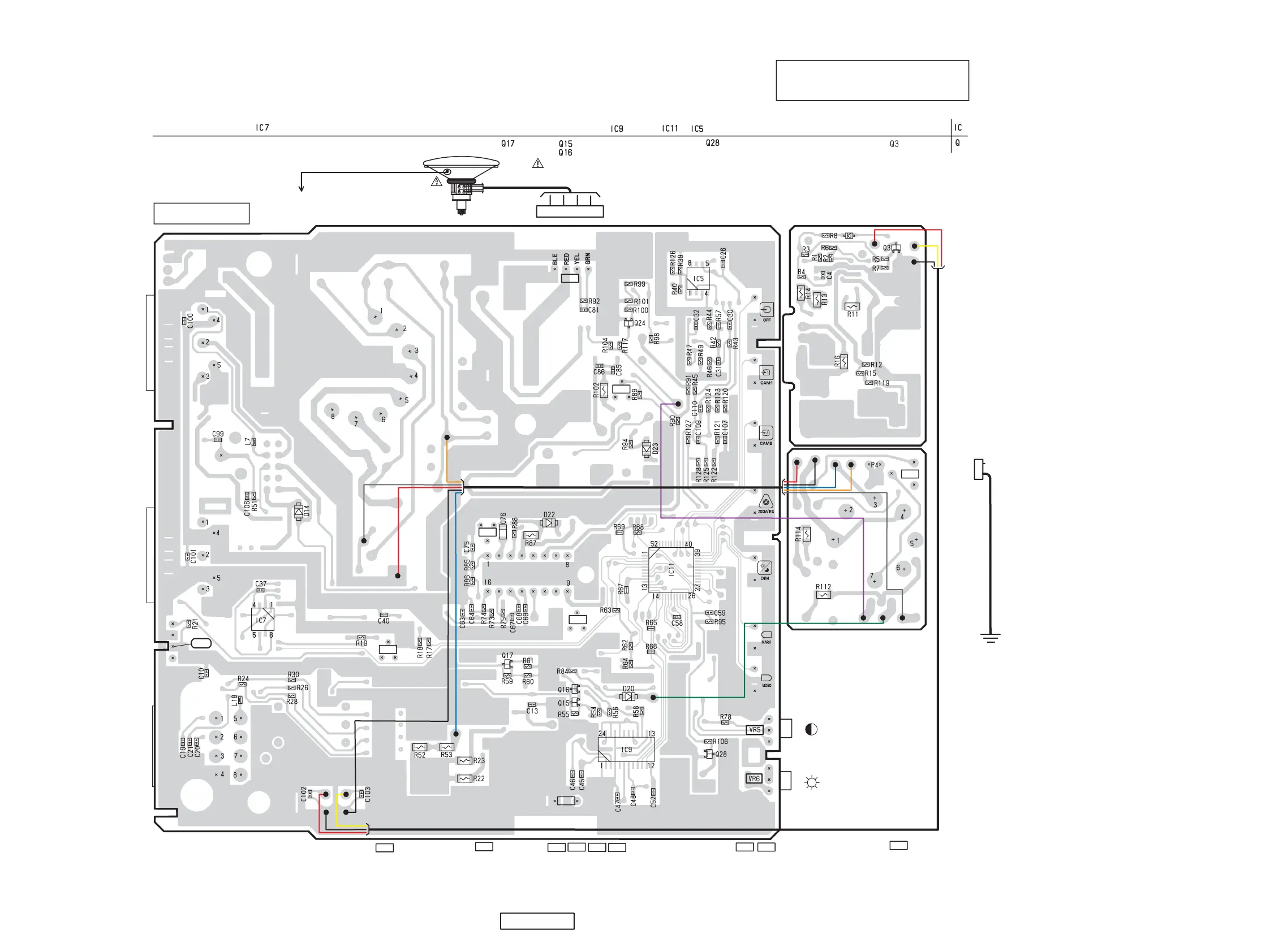
Note: All PWB consists of one piece of PWB.
Caution:
SOLDER SIDE: Parts on the solder side seen
from the solder side are indicated.
SOLDER SIDE
Main PWB(B1) / Switching PWB(B2) / Socket PWB(B3) Section:
To Main PWB P3
 Loading...