- 5 -
CJ-763E
pin 27: A VDD : - : Positive voltage supply for analog section.
pin 28: RESET : IN: Reset signal input.
pin 29: XT 2 : - : Crystal connection.
pin 30: XT 1 : - : Crystal connection.
pin 31: IC(VPP) : - : This terminal is connected directly with GND
at the operation mode usually.
pin 32: X 2 : - : The crystal connection.
pin 33: X 1 : - : The crystal connection.
pin 34: VSS : - : Negative voltage supply.
pin 35: AUX M IN :IN: Video manual operation selection SW input.
Active Low.
pin 36: MARK M IN :IN: Mark display manual operation SW input.
Active Low.
pin 37: DIM M IN :IN: Dimmer manual operation SW input. Active
Low.
pin 38: IRIS M IN :IN: The ON/OFF switch of backlighting compen-
sation is done if a high voltage that hangs
to this terminal is within at one second.
Moreover, the ON/OFF switch of an elec-
tronic zoom is done for one second or more
a high voltage that hangs to this terminal.
pin 39: CAM 2 M IN :IN: The second camera manual operation selec-
tion SW input. Active Low.
pin 40: CAM 1 M IN :IN: The first camera manual operation selection
SW input. Active Low.
pin 41: 23.7k PULSE : O : When this IC detects the electronic zoom
function, 23.7kHz are output from this ter-
minal.
pin 42: 10.0k PULSE : O : When this IC detects the backlighting com-
pensation function, 10kHz are output from
this terminal.
pin 43: IRIS OUT : O : This terminal outputs High synchronizing
with backlighting compensation pulse signal
output (10kHz).
pin 44: ACC OFF :IN: Power-off signal input.
pin 45: M OFF : IN: When this IC detects the voltage descent,
the selection by manual each selection SW
is released.
pin 46: I & Z ON : O : This terminal outputs L when both backlight-
ing compensation and an electronic zoom
functions are on.
pin 47: NC : O : Not in use.
pin 48: NC : O : Not in use.
pin 49: NC : O : Not in use.
pin 50: NC : O : Not in use.
pin 51: NC : O : Not in use.
pin 52: NC : O : Not in use.
052-3642-00 uPD780024ASGB-X46-8E System Controller
Terminal Description
pin 1: NC :IN: Not in use.
pin 2: NC : O : Not in use.
pin 3: POWER ON : O : Power ON signal output.
pin 4: AUS OUT : O : Video on signal output. When video manu-
al operation selection SW or Auto Select is
detected, High is output.
pin 5: CAM 2 OUT : O : The second camera on signal output. When
the second camera manual operation selec-
tion SW or Auto Select is detected, High is
output.
pin 6: CAM 1 OUT : O : The first camera on signal output. When the
first camera manual operation selection SW
or Auto Select is detected, High is output.
pin 7: DIMMER : O : Dimmer control signal output.
pin 8: EEP CS : O : The chip select signal output to the EEP-
ROM.
pin 9: VSS 0 : - : LED power ground.
pin 10: VDD 0 : - : Positive voltage supply.
pin 11: EEP DI :IN: The serial data input from the EEP-ROM.
pin 12: EEP DO : O : The serial data output to the EEP-ROM.
pin 13: EEP CK : O : The clock pulse output to the EEP-ROM.
pin 14: SI :IN: Serial data input.
pin 15: OSD SO : O : The serial data output to the on screen dis-
play IC.
pin 16: OSD SCK : O : The clock pulse output to the on screen
display IC.
pin 17: OSD CS : O : The chip select signal output to the on
screen display IC.
pin 18: CAM 1 A IN :IN: The first camera Auto Select input. Active
Low.
pin 19: DIM A IN :IN: Dimmer signal input. Meanwhile, when this
terminal becomes Low when the first cam-
era, the second camera or the video has
been selected, the dimmer signal output ter-
minal becomes High.
pin 20: VDD : - : Positive voltage supply.
pin 21: A VSS : - : Negative voltage supply for analog section.
pin 22: CAM 2 A IN :IN: The second camera Auto Select input.
Active Low.
pin 23: PARKING : IN : The parking brake signal input.
pin 24: NC : O : Not in use.
pin 25: NC : O : Not in use.
pin 26: A Vref :IN: The reference voltage for internal ADC.
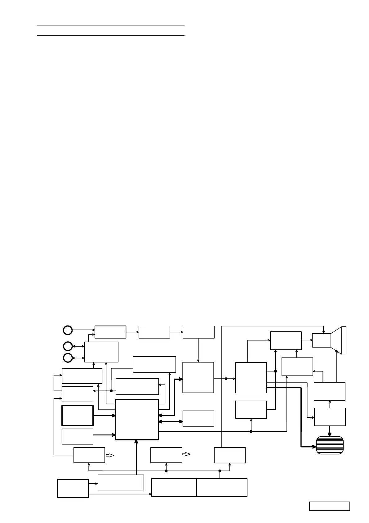
BLOCK DIAGRAM
IC8
IC5
IC6
IC15
IC9,IC17
IC13
Q15,Q16
Q23,Q28
Q29
T2
CRT
Q26,Q27
Q24,Q25
IC7
IC14
IC10,IC12
IC11
IC3,IC4
Q7,Q8,Q9,Q10,Q11
Q1,Q2,Q3
IC1,Q4,Q5
IC2,Q6
J4
J1
J3
J2
Q18,Q19
IC7
RY1,Q12,Q13
Q707,Q715,Q716
Camera 1
Video amp
Video output
Video clamp
On screen
display
control
Horizontal
Vertical
Synchronous
OSC.
Bright control
Horizontal
drive
High
voltage
Contrast
control
Heater
output
Monitor
Controller
Reset
Flash Memory
9V Power
supply
5V Power
supply
Power input
Excessive voltage
prevention circuit
Signal amp
External control input
ZOOM signal
IRIS signal
DC-DC converter
(12V output)
Yoke
Monitor
manual
operation
button
Each circuit
is supplied.
Each circuit
is supplied.
Camera 2
Video
9V Control
input
input
input
Camera switch
Video switch
AUX
 Loading...