-4-
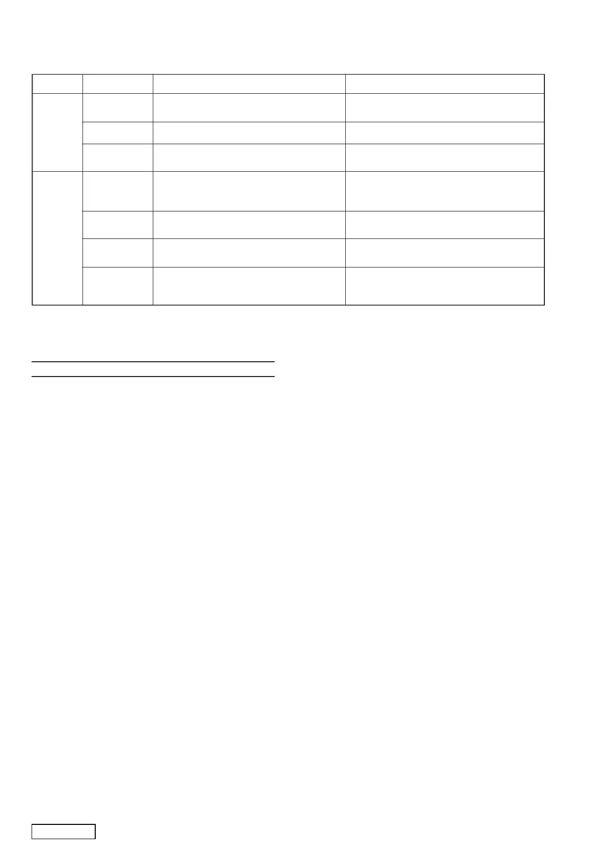
ERROR DISPLAYS
If an error occurs, one of the following displays is displayed. Take the measures described below to eliminate the problem.
Error Display Cause Measure
A CD is loaded upside-down inside the CD deck
and does not play.
Eject the disc then reload properly.
ERROR 6
ERROR 2
(iPod mode)
During the iPod analyse, failure to achieve the
iPod state or initialize the iPod driver, unusual
detection of iPod driver.
Switch to the iPod mode again, reset the unit and
iPod.
If an error display other than the ones described above appears, press the reset button.
A CD is caught inside the CD deck and is not
ejected.
This is a failure of CD deck mechanism.
ERROR 2
ERROR 3 A CD cannot be played due to scratches, etc. Replace with a non-scratched, non-warped disc.
CD/MP3/
WMA
USB/iPod
052-3996-00 LC8783G0PA-5AE8-E Main System Controller
EXPLANATION OF IC
Main section
CZ209/CZ209A
ERROR 3
(iPod mode)
During the playback, failure to achieve the iPod
state, unusual detection of iPod driver.
Switch to the iPod mode again.
ERROR 5
(iPod mode)
The connected iPod is not recognized. Disconnect and reconnect the iPod.
ERROR 7
(USB mode)
USB memory device format error. Disconnect and reconnect USB memory device. If
device still cannot be recognized, try replacing with
different USB memory device.
CD loading signal output for CD dirver IC.
System mute signal output.
Connect to LCD driver IC DI pin.
Connect to LCD driver IC DO pin.
The clock pulse output to the LCD dirver IC.
The chip enable signal output to the LCD
The serial data output to the volume IC.
Clock pulse output to the volume IC.
Positive supply voltage, connect to 5V.
The destination setting input.
The destination setting input.
Pefrence vlotage input for A/D converter.
Pefrence vlotage input for A/D converter.
USB connector mute detection signal.
The control signal output for V_BUS.
USB plug detection signal input.
The power supply control signal output for
LCD power and LCD backlight.
The power supply control signal output for
Key interrupting signal input.
The control signal output to internal audio
The control signal output to internal audio
Auto antena control signal output.
The telephone interrupt signal input.
Connect to USB micom RX pin.
Connect to USB micom TX pin.
illumination ON signal input.
Power supply ON signal input.
The power AMP OFFSET detection signal
Positive voltage supply, connect to 5V.
Backup detection signal input.
ACC detection signal input.
Remote controller signal input terminal.
32.768KHz crystal input, sub clock.
32.768KHz crystal output, sub clock.
13.5MHz crystal input, main clock.
13.5MHz crystal output, main clock.
Positive supply voltage, connect to 5V.
Connect to USB reset pin.
Connect to USB iPod-I/F pin.
Input terminal of A/D converter for key
Muting signal output to internal audio power
For CD text pin, Hi=OK, Lo=NG.
Connect to LC786920 DI pin.
Connect to LC786920 DO pin.
Connect to LC786920 CLK pin.
The chip enable signal output to LC786920.
Connect to LC786920 CD_MUTE pin.
Connect to LC786920 REST pin.
The tuner pack IF buffer control signal output.
Connect to USB_READY pin.
Connect to REG_READY pin.
Connect to CD driver IC MUTE pin.
Connect to CD driver IC VIN-SW pin.
Positive supply voltage, connect to 5V.
Inside limit switch signal input.
CD eject signal output for CD dirver IC.
 Loading...