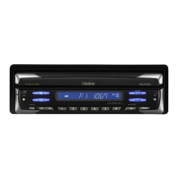
PN-3000P
PP-3000M
- 4 -
pin 16: ACC IN :IN: ACC ON flag input.
pin 17: PLL DO : O : PLL serial data output.
pin 18: NU : - : Not in use.
pin 19: B/T CTS :IN: BT module UART flow control.
pin 20: B/T RX :IN: BT module UART data input.
pin 21: TIME BASE :IN: Time base pulse input.
pin 22: B/T TX : O : BT module UART data output.
pin 23: PLL CE : O : PLL chip enable signal output.
pin 24: DIMMER : O : Dimmer output.
pin 25: PLL CK : O : PLL clock pulse output.
pin 26: NU : - : Not in use.
pin 27: DSP SCL : O : Clock pulse output to the DSP IC.
pin 28: DSP SDA :I/O:Serial data input/output for the digital sig-
nal processor.
pin 29: NDS TX : O : Serial data output for NDS.
pin 30: NDS RX :IN: Serial data input for NDS.
pin 31: NDS REQ 1 :IN: NDS request signal input.
pin 32: 6CD SLOT : O : Shutter light control signal output.
pin 33: 6CD SDA :I/O: Serial data input/output.
pin 34: 6CD SCL : O : Serial clock output.
pin 35: NU : - : Not in use.
pin 36: NU : - : Not in use.
pin 37: 6CD RESET : O : Reset pulse output.
pin 38: NU : - : Not in use.
pin 39: 6-CD REQ :IN: Request signal input for the 6CD-Chang-
er.
pin 40: NU : - : Not in use.
pin 41: NU : - : Not in use.
pin 42: NU :IN: Not in use.
pin 43: NU :IN: Not in use.
pin 44: NU :IN: Not in use.
pin 45: NU :IN: Not in use.
pin 46: NU : - : Not in use.
pin 47: NU : - : Not in use.
pin 48: CD ON : O : CD ON signal output.
pin 49: NU : - : Not in use.
pin 50: Power IC Stndb : O : The standby signal output to the power IC.
pin 51: LCD DO : O : Serial data output to the LCD controller.
pin 52: LCD CK : O : Clock pulse output to the LCD driver.
pin 53: LCD DI :IN: Serial data input from the LCD driver.
pin 54: LCD CE : O : Chip enable signal output to the LCD driv-
er.
pin 55: LCD RST : O : Reset pulse output to the LCD driver.
pin 56: VOL 3 :IN: Volume control pulse input from the rota-
ry encoder.
pin 57: VOL 2 :IN: Volume control pulse input from the rota-
ry encoder.
pin 58: VOL 1 :IN: Volume control pulse input from the rota-
ry encoder.
pin 59: FAN ON : O : The fan on signal output.
pin 60: VDD : - : Positive voltage supply.
pin 61: POWER ON :IN: Power ON signal input.
pin 62: GND : - : Ground.
pin 63: B/T TEST : O : BT module test.
pin 64: AUX ON :IN: AUX ON signal input.
pin 65: DIAG INPUT :IN: Diagnosis signal input from the audio pow-
er IC.
pin 66: B/T RTS : O : BT module UART flow control. AUX con-
nection detection.
pin 67: B/T TEST : O : BT module test.
pin 68: B/T BOOTE : O : BT module rewrite.
pin 69: B/T RESET P : O : BT module reset.
pin 70: NU : - : Not in use.
pin 71: NU :IN: Not in use.
pin 72: RDS CL 1 :IN: RDS 1 serial clock output.
pin 73: RDS DA 1 :IN: RDS 1 serial data input.
pin 74: GIX SYS ACC : O : 6CD-mechanism system ACC control.
pin 75: P IC MUTE : O : Muting-command output for the audio pow-
er IC.
pin 76: MH MUTE : O : Muting-command output for RDS and
DSP.
pin 77: M AGC BUFF :IN: DSP Keyed AGC detection.
pin 78: DSP RESET : O : Reset signal output to the DSP IC.
pin 79: MT S METER :IN: Input of internal A/D converter to monitor
the radio field strength for the Main-tun-
er.
pin 80: MT SAMPLE :IN : Main-tuner sample input.
pin 81: MT HOLD :IN: AF-hold-signal input from the Main-tuner.
And S-hold signal input from the DSP.
pin 82: EQ 1 :IN : The equalizer setting input.
pin 83: EQ 2 :IN : The equalizer setting input.
pin 84: EQ 3 :IN : The equalizer setting input.
pin 85: EQ 4 :IN : The equalizer setting input.
pin 86: NU :IN: Not in use.
pin 87: CD EJECT :IN: CD eject signal input.
pin 88: LOAD SW :IN: LOAD switch signal input.
pin 89: NU : - : Not in use.
pin 90: NU : - : Not in use.
pin 91: INI KEY :IN : Initializing command input.
pin 92: REMO A :IN: Steering wheel remote controller signal
input.
pin 93: REMO B :IN: Steering wheel remote controller signal
input.
pin 94: A GND : - : Analog ground.
pin 95: NU : - : Not in use.
pin 96: VREFI :IN: Reference voltage input.
pin 97: A VCC : - : Positive voltage supply for the internal
analog section.
pin 98: MT SCL :IN: Main-tuner control clock pulse.
pin 99: MT SDA :I/O:Serial data input/output for the Main-tun-
er.
pin100: DSP PAUSE :IN: DSP automatic mute control. L = mute on.

 Loading...
