EN
ENGLISH
Clarke
®
American Sanders Operator's Manual (EN) - CE 7 Pro, SE7 Pro, CE7 Pro+, SE7 Pro+ - FORM NO. 71376A - 7 -
Machine Set-up
Fig. 1.1 OPERATING HANDLE
The operating handle provides control and comfort to the
sanding experience (all models). On models 07170A
and 07176A, the handles may be set to a greater height
depending on preference. Remove the 4 screws secur-
ing the handle to the machine. Raise the handle until
the holes align then reinstall the 4 screws.
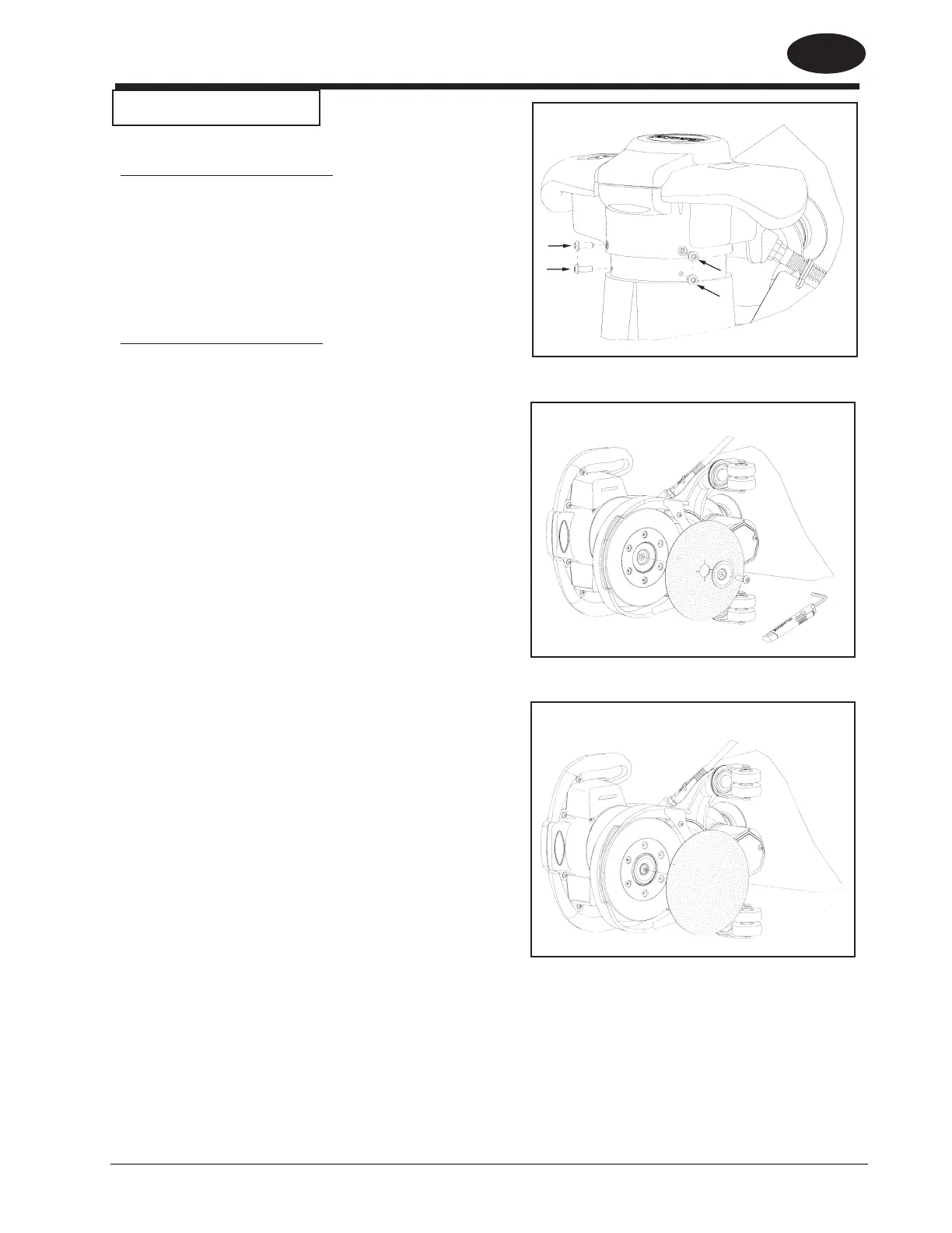
Fig. 2.1, 2.2 Abrasive Driver
The unit will accept either 7" hook and loop or 7"x7/8"
center hole abrasive disc. Motion is delivered to the
abrasive through a replaceable spring steel sanding disc
(11226A) having a medium hook surface (39864A). The
unique geometry provides a flat finish and smooth
sanding experience, reducing objectionable scratches.
The unit is equipped with a retaining screw, washer, and
onboard wrench for use with 7" x 7/8" abrasive. When
installing abrasive disc, take care to center disc on
driver.
NOTE: When using 7" x 7/8" abrasive, hold the sanding
disc while tightening the retaining screw. Do not over
tighten or removal will be difficult.
To avoid injuring the hook surface on the driver when
sanding thick paint, varnish or wax, it is recommended
you stack two discs on the driver using a course open
coat abrasive.
Figure 1.1
Figure 2.1
Figure 2.2
7" x 7/8" Mounting Hole
7" Hook and Loop
 Loading...