Disassembly
Removing the System Memory (RAM) 2 - 11
2.Disassembly
Removing the System Memory (RAM)
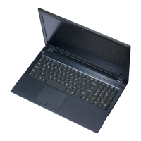
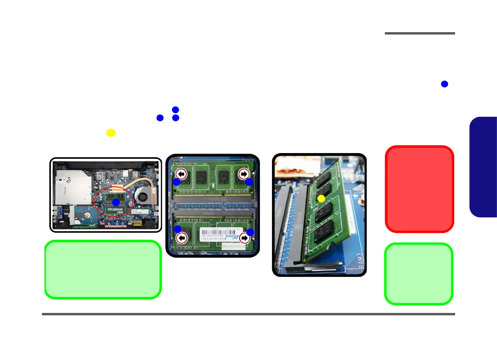
Figure 7
RAM Module
Removal
a. The RAM modules will
be visible at point
on the mainboard.
b. Pull the release lat-
ches.
c. Remove the module.
Contact Warning
Be careful not to touch
the metal pins on the
module’s connecting
edge. Even the cleanest
hands have oils which
can attract particles, and
degrade the module’s
performance.
The computer has two memory sockets for 260 pin Small Outline Dual In-line Memory Modules (SO-DIMM) supporting
DDR4 Up to 2133 MHz. The main memory can be expanded up to 32GB. The total memory size is automatically detect-
ed by the POST routine once you turn on your computer.
Memory Upgrade Process
1. Turn off the computer, turn it over to remove the battery (page 2 - 5) and bottom cover (page 2 - 7).
2. The RAM modules will be visible at point on the mainboard (Figure 7b
).
3. Gently pull the two release latches ( & ) on the sides of the memory socket in the direction indicated by the
arrows (Figure 7b).
4. The RAM module will pop-up (Figure 7c), and you can then remove it.
a.
1
b.
c.
2
3
4
Single Memory Module Installation
If your computer has a single memory
module, then insert the module into the
Channel 0 (JDIMM1 / RAM1) socket.
2 3
 Loading...