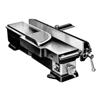
OPERATING INSTRUCTIONS FOR 24 INCH JIG SAW
LUBRICATION
To prepare for shipping, the oil has been removed from this tool. Do not run until refilled with a good grade
of oil similar to S.A.E. No. 30. To refill, remove the pipe plug from filler pipe in front of crank case and pour in
SLIGIITLY LESS THAN ONE PINT OF OIL.
TIIIS FILLING OF OIL SHOULD LAST INDEFINITELY, BUT IF MORE OIL IS ADDED, POUR IN
ENOUGH TO HAVE IT JUST VISIBLE AT THE BOTTOM OF THE FILLER PIPE.
Any oil in excess of the above amount will be wasted as same will pass from crank case either through
breather hole or vents around piston rod until required level is reached. The crank case mechanism and main bear-
ing are lubricated by means of an oil pressure system. The pressure is produced by a simple pump arrangement
in combination with the mechanism in crank case which pumps and forces the oil from the bottom of the crank
case to all parts requiring lubr'cation in the crank case.
The square upper pump piston rod should be oiled or greased and a few drops of oil should be applied through
the hole in the pump tube cap occasionally.
Periodic greasing of the table trunnions is recommended.
:_ :_- REASSEMBLY INSTRUCTIONS
This jig saw has once been completely aszemblzd at the factory and to avoid breakage through rough hand-
ling while in transit the table has been removed.
Looking at the under side of this table you wil_. note that one pair of trunnion bosses is close to one edge of
the table. To reassemble table, p:ace the tab!e on the trunnions with these bosses toward the back.
The four mounting screws are in the cloth bag. Place the plain washer next to the trunnion boss, then the
lock washer before tightening screws.
The blade has been pushed up into the upper chuck to avoid breakage.
CAUTION. For shipping purposes the upper pump tube assembly has been lowered and the cIamp bolt tight-
ened.
To raise or turn this tube loosen the clamp bolt and move the assembly by hand.
Do not turn pump tube with WRENCII OR PLIERS.
SPEEDS
The large pulley ismounted with large d:ameter next to the crank case and the small pulley is mounted on
a 1750 R.P.M. motor with the small diameter adjacent to the motor. This will give approxin:ate speeds of 1750_
1284--926 and 657. 926 and 1284 are the recommended speeds. A 1/3 horsepower motor is recommended for this
Sav,_. , _.-
PULLEY ON CRANK CASE MUST RUN IN DIRECTION INDICATED BY ARROW SIIOWN ON OUT-
SIDE OF CRANK CASE SIIAFT BEARING HOUSING.
MOTOR I_IOUNTING
The motor mounting is in two parts, the front eltd b_ing the conventional floating type pivoted in adjustable
clips. The rear part has an adjusting screw so weight or motor can berelieved from the belt and b_arings.
,. . , PUMP MECHANISM
The upper guide tube and pump mechanism is mounted in a housing which is fastened in the overarm by
means of taper pointed screws which reginter against the angular surfaces of a grcove in a pivot pilot which is
bolted to thd housing.
Loosening the "screws p:rmits the entire a=sembly to be turned radially. Removing the screws permits the
removal of the assembly. Air for blowing dust away from the work is provided through a tube concealed in the
pump tube. Additional air is exhau=ted th'ough chuck jaws in upper guide tube.
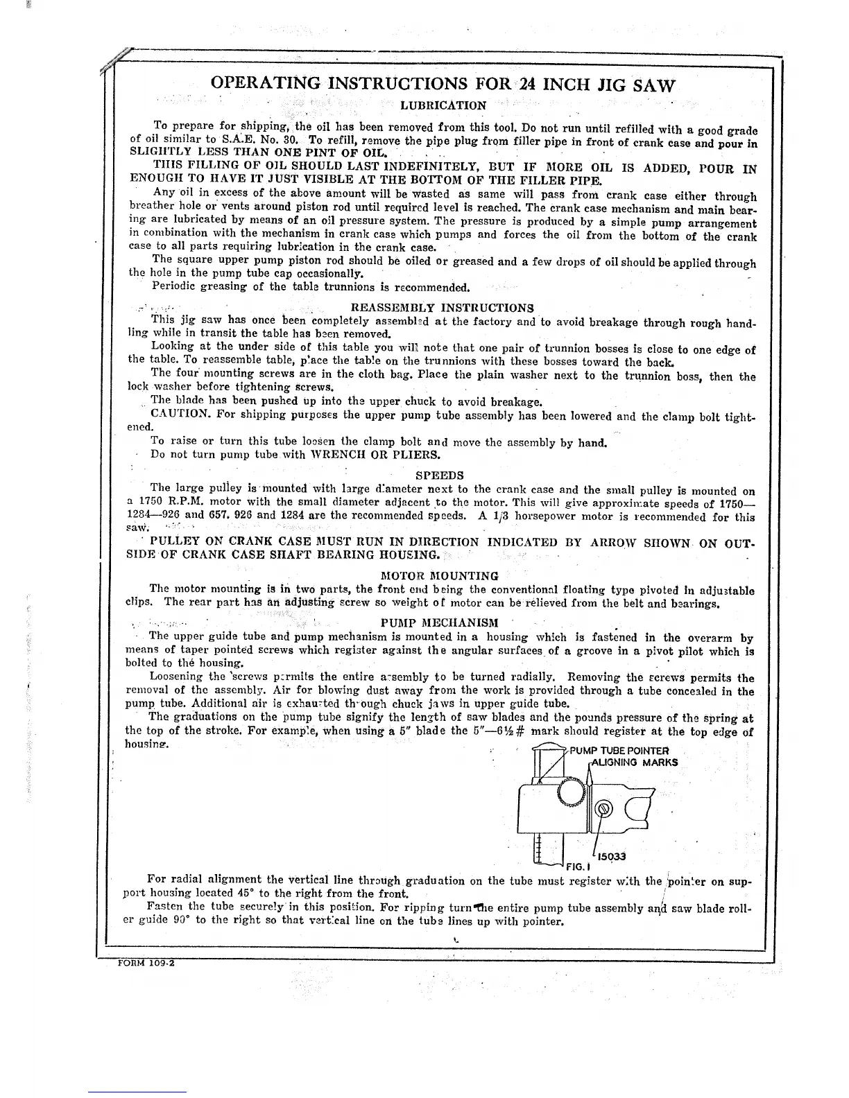
The graduations on the pump tube signify the length of saw blades and the pounds pressure of the spring at
the top of the stroke. For examp',e, when using a 5" blade the 5"--6½# mark should register at the top edge of
housing.
PUMP TUBEPOINTER
-ALIGNING MARKS
/jso
FIG.
For radial alignment the vertical line thrDugh graduation on the tube must register w:th the poin._er on sup-
port housing located 45 ° to the right from the front.
Fasten the tube secure!y in this posi._ion. For ripping turn_he entire pump tube assembly ar_i saw blade roll-
er guide 90 ° to the right so that vart'cai line on the tuba lines up with pointer.
%
F-O B.M 109.2
 Loading...