m¢
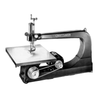
JIG SAW WITH TENSIONER--MODEL 103.0404 ONLY
A blade tensioner is provided so that correct tensioRcan be obtained when using various sizes of blades.
Tension can be varied with blade in place and while machine is in operation.
Improper tension wiU cause vibration which will disappear when correct point is reached.
To increase or decrease the tension of the saw blade, loosen pump tube clamp screw and turn ball crank to
the right or left. Lock clamp screw when desired tension is reached.
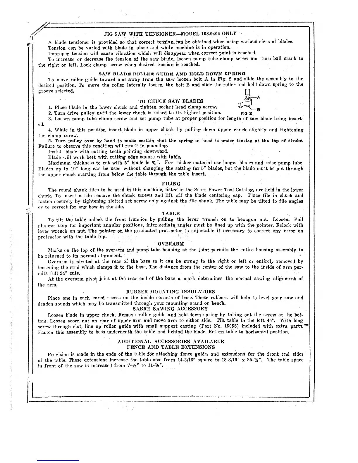
$AW 13LAD_ I_OLLE_ GLTID_ AND IIOI_D DOWN _P I_I1N_
To move roller guide toward and away from the saw loosen bolt A in Fig. 2 and slide the a_semb'.y to the
desired position. To move the roller laterally loosen the bolt B and slide the roller and hold down spring to the
groove selected. _--A
TO CIIUCK SAW BLADES
1. Place blade in the lower chuck and tighten socket head clamp screw. --B
2. Turn drive pulley uI,til the lower chuck is raised to its highest position. FIG.2
3. Loosen pump tube clamp screw and set pump tube at proper position for length of saw blade b_ing insert-
ed.
4. While in this position insert blade in upper chuck by pulling down upper chuck slightly and tightening
the clamp screw.
6, Turn pulley over by hand to make eertaln that the sprlng in head i_ under tenslon at the top of stroke.
Failure to observe this condition will resu:t in pounding.
Install blade with cutting teeth pointing downward.
Blade will work best with cutting edge square with table.
Maximum thickness to cut with 5" blade is _A". For thicker material use longer blades and raise pump tube.
Blades up to 10" long can be used without changing the setting for 5" blades, but the blade mu_t be put through
the upper chuck starting from below the table through the table insert.
FILING
The round shank files to be used in this machine, listed in the Sears Power Tool Catalog, are held in the lower
chuck. To insert a file remove the chuck screws and lift off the blade centering cap. Place file in chuck and
fasten securely by tightening slotted set screw only against the file shank. The table may be tilted to file angles
or to correc_ for any bow in the file,
TABLE
To tiltthe table unlock the front trunnion by pulling the lever wrench on to hexagon nut. Loosen. Pull
plunger stop for important angular positions,intermediate angles must be lined up wlth the pointer. Rrlock wlth
lever wrench on nut. The pointer on the graduated protractor is adjustable if necessary to correct any error on
protractor with the table top.
OVERARM
Marks on the top of the overm'm and pump tube housing at the joint permits the entire housing aszembly to
be returned to its normal alignment.
Overarm is pivoted at the rear of the base so it can be swung to the right or left or entirdy removed by
loosening the stud which clamps it to the base, The distance from the center of the saw to the inside of arm per-
mits full 24" cuts.
At the overarm pivot, joinb at the rear end of the base a mark determines the normal sawing alig'nm_nt of
the arm.
RUBBER MOUNTING INSULATORS
Place one in each cored recess on the inside corners of base: These rubbers will help to level your saw and
deaden sounds which ,nay be transmitted through your mount_n_ stand or bench.
SABRE SAWING ACCESSORY
Loosen blade _n upper chuck. Remove roller guide and hold-down spring by taking out the screw at the b0t-
tom. Loosen acorn nut on rear of upper arm and move arm to either side. Tilt table to the left 45 ° . With long
screw through slot, line up roller guide with small support casting (Part No. 15055) included with extra part_."
Fasten this assembly to boss underneath the table and behind the blade. Return table to horizontal position.
ADDITIONAL ACCESSORIES AVAILABLE
FENCE AND TABLE EXTENSIONS
Provision is made in the ends of the table for attaching fence guides and ext_nsion_ for the front _nd sides
of the table. These extensions increase the table size from 14-3/16" square to 18-31_16 " x 25-1,_ ". The table space
in front of the saw is increased from 7-_/_" to 11-_/_ ".
 Loading...