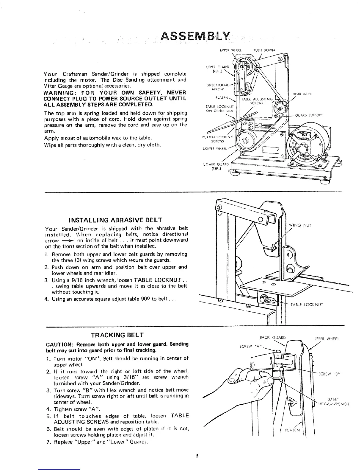
ASSEMBLY
Your Craftsman Sander/Grinder is shipped complete
including the motor, The Disc Sanding attachment and
Miter Gauge are optional accessories.
WARNING: FOR YOUR OWN SAFETY, NEVER
CONNECT PLUG TO POWER SOURCE OUTLET UNTIL
ALL ASSEMBLY STEPS ARE COMPLETED.
The top arm is spring loaded and held down for shipping
purposes with a piece of cord. Hold down against spring
pressure on the arm, remove the cord and ease up on the
arm,
Apply a coat of automobile wax to the table,
Wipe all parts thoroughly with a clean, dry cloth.
PLATEN LOCKING
SCREWS
LOWER
PUSH DOWN
REAR IDLER
INSTALLI NG ABRASIVE BELT
Your Sander!Grinder is shipped with the abrasive belt
installed. When replacing belts, notice directional
arrow _ on inside of belt.., it must point downward
on the front section of the belt when installed,
1. Remove both upper and lower belt guards by removing
the three (3) wing screws which secure the guards.
2. Push down on arm and position belt over upper and
lower wheels and rear idler.
3. Using a 9/16 inch wrench, loosen TABLE LOCKNUT.,
• swing table upwards and move it as close to the belt
without touching it.
4. Using an accurate square adjust table 90 ° to belt,,,
WING NUT
TABLE LOCKNUT
TRACKING BELT
CAUTION: Remove both upper and lower guard, Sanding
belt may cut into guard prior to final tracking.
1. Turn motor "ON". Belt should be running in center of
upper wheel,
2, If it runs toward the right or left side of the wheel,
loosen screw "'A'" using 3/t6" set screw wrench
furnished with your Sander/Grinder.
3. Turn screw "B" with Hex wrench and notice belt move
sideways, Turn screw right or left until beitt is running in
center of wheel.
4. Tighten screw "'A',
5. If belt touches edges of table, loosen TABLE
ADJUSTING SCREWS and reposition table,
6. Belt should be even ,with edges of platen if it is not,
loosen screws holding platen and adjust it,
7. Replace "Upper" and "Lower" Guards,
BACK GUARD
SCREW "A"
UPPER WHEEL
 Loading...