EasyManua.ls Logo

Craftsman 139.18595 User Manual

Craftsman 139.18595
80 pages
To Next Page IconTo Next Page
To Previous Page IconTo Previous Page
Page #17 background imageLoading...
Page #17 background image
17
To prevent possible SERIOUS INJURY or DEATH from
electrocution:
Be sure power is not connected BEFORE installing door
control.
Connect ONLY to 24 VOLT low voltage wires.
To prevent possible SERIOUS INJURY or DEATH from a
closing garage door:
Install door control within sight of garage door, out of
reach of children at a minimum height of 5 feet
(1.5 m), and away from all moving parts of door.
NEVER permit children to operate or play with door
control push buttons or remote control transmitters.
Activate door ONLY when it can be seen clearly, is
properly adjusted, and there are no obstructions to door
travel.
ALWAYS keep garage door in sight until completely
closed. NEVER permit anyone to cross path of closing
garage door.
WARNING
CAUTION
WARNING
WARNING
INSTALLATION STEP 6
Install the Door Control
Locate door control within sight of door, at a
minimum height of 5 feet (1.5 m) where small
children cannot reach, away from moving parts of
door and door hardware. If installing into drywall, drill
5/32" holes and use the anchors provided. For
pre-wired installations (as in new home
construction), it may be mounted to a single gang
box (Figure 2).
1. Strip 7/16" (11 mm) of insulation from one end of
bell wire and connect to the two screw terminals
on back of door control by color: white wire to
2 and white/red wire to the 1.
2. Remove cover by gently prying at slot in top of the
cover with a small flat head screwdriver. Fasten
with 6ABx1-1/4" self-tapping screws (drywall
installation) or 6-32x1" machine screws (into gang
box) as follows:
Install bottom screw, allowing 1/8" (3 mm) to
protrude above wall surface.
Position bottom of door control on screw head
and slide down to secure. Adjust screw
for snug fit.
Drill and install top screw with care to avoid
cracking plastic housing. Do not overtighten.
Insert top tabs and snap on cover.
3. (For standard installation only) Run bell wire up
wall and across ceiling to motor unit. Use
insulated staples to secure wire in several places.
Do not pierce wire with a staple, creating a short
or open circuit.
4. Strip 7/16" (11 mm) of insulation from end of bell
wire. Connect bell wire to the quick-connect
terminals as follows: white to white and white/red
to red.
NOTE: When connecting multiple door controls to
the opener, twist same color wires together. Insert
wires into quick-connect holes: white to white and
red/white to red.
5. Position the antenna wire as shown.
6. Use tacks or staples to permanently attach
entrapment warning label to wall near door
control, and manual release/safety reverse test
label in a prominent location on inside of
garage door.
NOTE: DO NOT connect power and operate
opener at this time. The trolley will travel to the full
open position but will not return to the close
position until the sensor beam is connected and
properly aligned.
Drywall Anchors
Insulated
Staples
Screw 6ABx1-1/4"
Control Panel (std installation)
Screw 6-32x1"
Control Panel (pre-wired)
HARDWARE SHOWN ACTUAL SIZE
Outside Keylock Accessory Connections
To opener quick-connect terminals: white to white;
white/red to red.
To Replace,
Insert Top
Tabs First
To Remove,
Twist
Here
PRE-WIRED
INSTALLATION
REMOVE & REPLACE COVER
L
O
C
K
L
I
G
H
T
Figure 1 Figure 2
24 Volt
2-Conductor
Bell Wire
PREMIUM
CONTROL CONSOLE
Terminal
Screws
(BACK VIEW)
Top
Mounting
Hole
Bottom
Mounting
Hole
WHITE
2
RED
1
Bell
Wire
Strip wire 7/16" (11 mm)
7/16" (11 mm)
Red GreyWhite
Lock
Light
Lighted
Push Button
L
O
C
K
L
IG
H
T
2-Conductor
Bell Wire
Quick-Connect
Terminals
Antenna
To release wire, push in
tab with screwdriver tip
Door Control
Connections

Table of Contents

Question and Answer IconNeed help?

Do you have a question about the Craftsman 139.18595 and is the answer not in the manual?

Craftsman 139.18595 Specifications

General IconGeneral
TypeChain Drive
Horsepower1/2 HP
Frequency60 Hz
Remote ControlYes
Voltage120V

Summary

Introduction to Garage Door Opener Manual

Safety Symbol and Signal Word Review

Explains safety symbols and signal words used throughout the manual.

Assembly Guide for Garage Door Opener

Assemble the Rail and Install the Trolley

Connects rail sections and mounts the trolley assembly for opener function.

Fasten the Rail to the Motor Unit

Secures the assembled rail to the main motor unit for structural integrity.

Install the Idler Pulley

Attaches the idler pulley to the rail end, essential for chain/cable movement.

Install the Chain/Cable

Connects the chain or cable to the trolley and sprocket for power transmission.

Tighten the Chain

Adjusts chain tension for proper operation and to prevent sprocket noise.

Installation Procedures for Garage Door Opener

Preparing Your Garage Door

Essential pre-installation steps including door balance checks and disabling locks.

Tools Needed for Installation

Lists all necessary hand tools required for assembly and installation procedures.

Planning Your Installation

Identifies door type, height, and garage area conditions for proper opener placement.

Carton Inventory

Lists all parts included in the opener packaging for initial verification.

Hardware Inventory

Details all hardware components required for assembly and installation.

Determine the Header Bracket Location

Identifies the correct mounting position for the header bracket based on door type.

Install the Header Bracket

Secures the header bracket to the wall or ceiling structural support.

Attach the Rail to the Header Bracket

Connects the assembled rail to the mounted header bracket.

Position the Opener

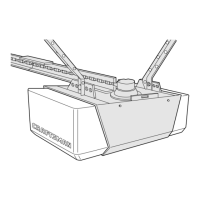
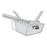
Sets the correct height and placement of the motor unit for optimal operation.

Hang the Opener

Mounts the opener securely to the ceiling or wall supports using hanging brackets.

Install the Door Control

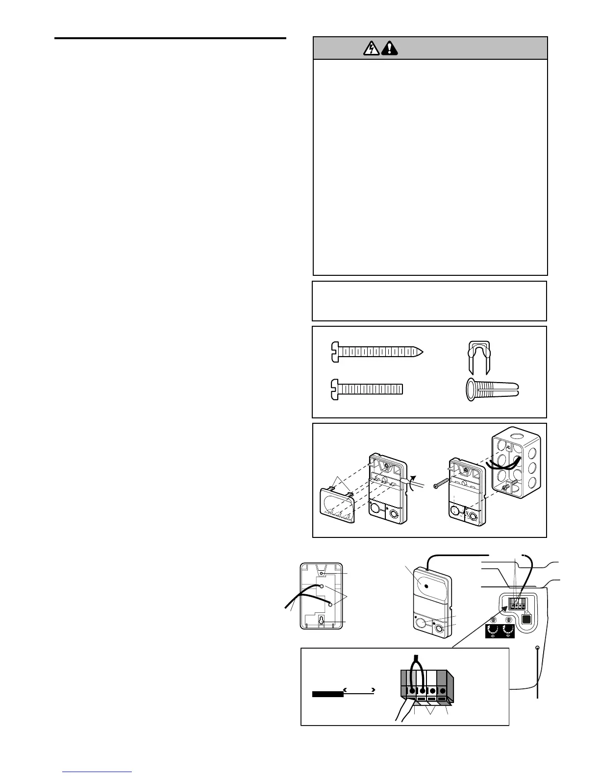
Mounts the wall-mounted control panel and wires it to the opener.

Install Lights

Installs the light bulbs and lenses into the motor unit's end panel.

Attach the Emergency Release Rope and Handle

Installs the manual release mechanism for disengaging the trolley.

Electrical Requirements

Details power connection standards, grounding, and wiring compliance.

Install The Protector System® (Safety Reversing Sensors)

Installs and aligns the safety reversing sensors for obstruction detection.

Install Brackets for Safety Sensors

Describes different methods for mounting the safety sensor brackets.

Mount and Wire the Safety Sensors

Connects sensor wires to the motor unit and aligns the sensors for proper function.

Fasten the Door Bracket

Attaches the door bracket to the garage door for connecting the opener arm.

Connect Door Arm to Trolley

Links the door arm sections to the opener's trolley assembly.

Adjustment Procedures for Garage Door Opener

Adjust the UP and DOWN Travel Limits

Sets the open and close positions of the garage door for safe operation.

Adjust the Force

Sets the force required to open and close the door, ensuring proper reversal.

Test the Safety Reversal System

Verifies the door reverses upon striking an obstruction, a critical safety feature.

Test The Protector System®

Verifies the function of the safety reversing sensors by testing the beam path.

Operation of Your Garage Door Opener

General Operation Safety Instructions

Key safety guidelines to follow when operating the garage door opener.

Using Your Garage Door Opener

Explains how to activate the opener using remotes, wall controls, and keypads.

Using the Wall-Mounted Door Control

Details operation of the control console, including light and lock features.

Opening the Door Manually

Instructions for operating the garage door manually in case of power failure.

Care and Maintenance of Your Opener

Limit and Force Adjustments

Notes on how weather affects settings and where to find adjustment information.

Maintenance Schedule

Recommended checks and tasks performed monthly, twice yearly, and yearly.

Remote Control Battery Replacement

Instructions for safely replacing the battery in the remote control transmitter.

Troubleshooting Garage Door Opener Issues

Common Problems and Solutions

Addresses common opener issues like sensor malfunctions, remote activation, and door reversal.

Diagnostic Chart

Lists error codes (flashes) and their meanings for diagnosing opener issues.

Programming Your Garage Door Opener

Add or Reprogram a Hand-held Remote Control

Steps to pair additional remote controls with the garage door opener.

Erase All Codes From Motor Unit Memory

Procedure to clear all previously programmed remote controls from the opener.

Add, Reprogram or Change a Keyless Entry PIN

Instructions for programming and managing the keypad entry PIN.

Garage Door Opener Repair Parts

Rail Assembly Parts

Identifies components of the opener's rail system for replacement.

Installation Parts

Lists various parts used during the installation process.

Motor Unit Assembly Parts

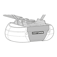
Details components of the main motor unit for repair or identification.

Optional Accessories for Garage Door Opener

Available Accessories

Lists and describes optional add-on items for enhanced opener functionality.

Warranty Information for Garage Door Opener

Sears Warranty Terms

Outlines the limited warranties for the opener, motor, and belt, including coverage details.

Related product manuals