7
ENGLISH
OPERATION
WARNING: To reduce the risk of serious personal
injury, turn unit off and disconnect it from
power source before making any adjustments or
removing/installing attachments or accessories.
An accidental start-up can causeinjury.
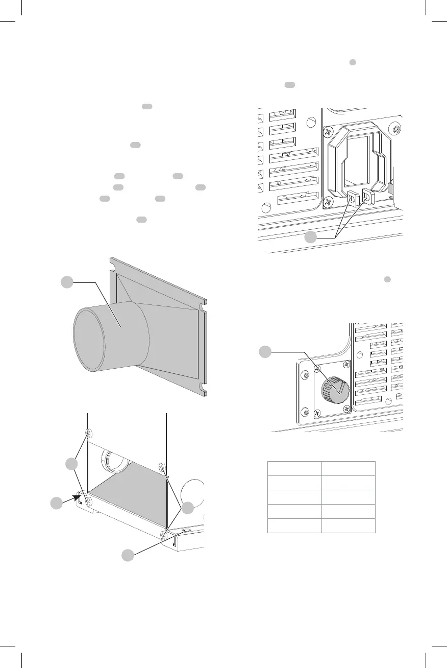
Fastening Jointer to Supporting Surface
(Fig. M)
If during operation, there is any tendency for the jointer
to tip over, slide or “walk” on the supporting surface, the
jointer must be secured to the supporting surface. Four
holes (two of which are shown at
22
Fig.M, are provided
for thispurpose.
Dust Collector Hose Adapter (Fig. L, M)
A dust collector hose adapter
23
is supplied with the
jointer to help connect it to a standard 2" (51 mm) vacuum
hose. To assemble the adapter:
1. Remove two screws
25
. Loosen screws
26
.
2. Slide adapter’s slots
24
under loosened screws
26
.
3. Tighten screws
26
when adapter
23
is in
properlocation.
4. Replace and tighten screws
25
.
NOTICE: Do not install this vacuum hose adapter
unless you will be using a dust collector.
Fig.L
23
Fig.M
25
26
22
22
Stopping and Starting the Jointer (Fig. N)
To turn the planer on, lift up the switch
5
. The planer locks
on automatically. To turn the tool off, press the switch
down. Two holes
27
are provided in the bottom of the
switch housing for locking off the planer with apadlock.
Fig.N
27
Variable Speed Control (Fig. O)
Your jointer is supplied with variable speed control
6
that
enables you to operate the machine at cutterhead speeds
between 6000 and 11000 RPM. Speed indicators of 1, 2, 3, 4
and 5 are provided on the speeddial.
Fig.O
6
Speed Approximate
RPM
1 6000
2 7250
3 8800
4 9750
5 11000
Speed Selection Chart
Use the speed selection chart to determine the proper
setting for yourworkpiece.

 Loading...