DO GUIDE
Install the Cable Retention Plate
Install the cable retention plate to the underside of the mounting surface as shown in the following diagram. The cable retention plate should be located
approximately 3 inches (76 mm) from the DOCK CONNECTIONS ports.
CCS-UC-300
Crestron
®
SR Next Generation Room System for Skype
®
for Business
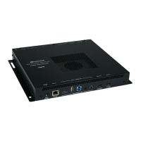
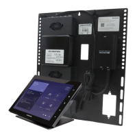
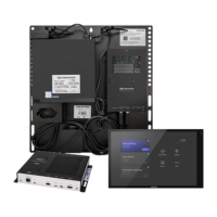
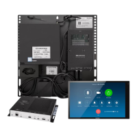
DO Install the Device
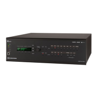
The CCS-UC-300 consists of an enclosure (CCS-UC-CODEC-TS-300) that is secured to a mounting surface such as a table, and an “engine”
(CCS-UC-CODEC-ENGINE) that mounts under the mounting surface. Crestron strongly recommends using the included TS-SMK to install and secure the
enclosure to the mounting surface.
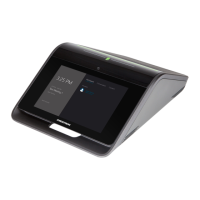
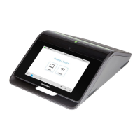
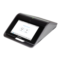
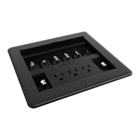
Install the Microsoft Surface
®
Pro 4 Computer in the Enclosure
Install the Microsoft Surface Pro 4 tablet in the enclosure as shown in the installation video at https://vimeo.com/crestron/review/215565790/b4c0cf3795.
Position the Enclosure and Engine on a Table
The enclosure can be secured to a surface with the included TS-SMK swivel mount kit (recommended), or placed on a surface.
• Secure the enclosure to the surface with the TS-SMK.
1. Refer to the TS-SMK DO Guide (Doc. 7966) at www.crestron.com/manuals for instructions on installing the TS-SMK.
2. Position and secure the engine to the underside of the mounting surface using four mounting screws (not included). Refer to the following image
when positioning the engine.
NOTE: The engine should be positioned so the DOCK CONNECTIONS ports are no further than 9 inches (228 mm) from the center of the TS-SMK.
• Place the enclosure on the surface.
1. Place the enclosure on a mounting surface, within 9 inches (228 mm) of the engine’s planned location under the mounting surface as shown in the
following diagram.
2. Drill a 1-1/16-inch (27 mm) hole and feed the cables from the enclosure through the hole.
3. Position and secure the engine to the underside of the mounting surface using four mounting screws (not included). Refer to the following image
when positioning the engine.
NOTE: The engine should be positioned so the DOCK CONNECTIONS ports are no further than 9 inches (228 mm) from the center of the hole
drilled in step 2.
DO Check the Box
QUANTITY PRODUCT COLOR PART NUMBER
CCS-UC-CODEC-ENGINE Only
1 Cable, HDMI, 6' (1.83 m) 2048186
1 Cable, HDMI, 20' (6.10 m) 2048185
1 Cable, RJ-45 Male - RJ-45 Male, 12' (3.66 m) 2033988
1 Power Cord, 6' 7" (2 m) 200113 4
1 Power Pack, 15 Vdc 6 A, 100-240 Vac 2048306
1 Retention Bracket, Cable 2048360
1 Retention Plate, Cable 2048359
1 Swivel Mount Kit, TS-SMK 6508254
6 Tie Wrap 2047935
CCS-UC-CODEC-TS-300 Only
1 Cover, Plastic, Cable Exit 2047952
2 Foot, Rubber 2048005
4 Screw, 0-42 x 1/8", Pan Head, Phillips, PLASTITE
®
2048142
4 Screw, 2-28 x 1/4", Pan Head, Phillips, Thread Forming Black 2007117
10 Screw, 4-20 x 1/4", Pan Head, Phillips, Thread Forming 2007134
3 Tie Wrap 2047935
1 Tool, Screwdriver 4526579
Enclosure
TS-SMK
Cable retention plate
3.00 in
(76 mm)
Enclosure
9.00 in max
Cable
retention plate
Cable bundle
from enclosure
Engine
3.00 in
(76 mm)
9.00 in max
Cable
retention plate
Engine
3.00 in
(76 mm)
Enclosure
TS-SMK