34
3-2) COLOR NOISE REDUCTION
• Adjustment Procedure
1. Preparation
1) Supply the Color bar signal to the VIDEO LINE IN JACK.
2) Supply 5V to RY05.
2. Adjustment
1) Set the VCR to the STOP(EE) Mode.
2) Set the Oscilloscope to the chop mode.
Connect CH1 to the V-OUT(RY09) and CH2 to the YNR TP (RY05) and trigger the scope with the signal from CH1.
3) Adjust RY91 until Color signal becomes minimum.
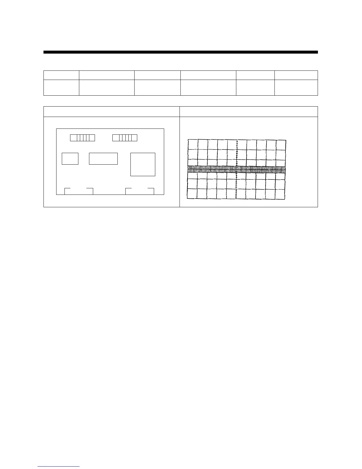
Location of Adjustment Parts Observation Waveform
Y/C PCB Horizontal Axis : 10µS/DIV
Vertical Axis : 50 mV/DIV
Mode Adjustment parts Check point Test equipments Test tape Input signal
EE RY 91 PY09 Signal gen. Color Bar
Oscilloscope
CH-2(PY09(NR)
Horizontal:10µs/DIV
Vertical:50mv/DIV
Y/C PCB SOLDER SIDE
PY05
PY09
IY03 IY01
IY02
⊕RY91
PAY01 PAY02
 Loading...