Installation and Configuration Manual
16
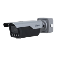
Alarm output, connecting to barrier, and
alarm output devices such as alarm light.
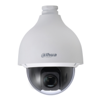
Alarm input, connecting to vehicle
detector, IR detector, induction loop, and
more.
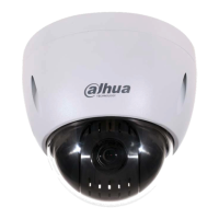
Connects to displays and other external
devices.
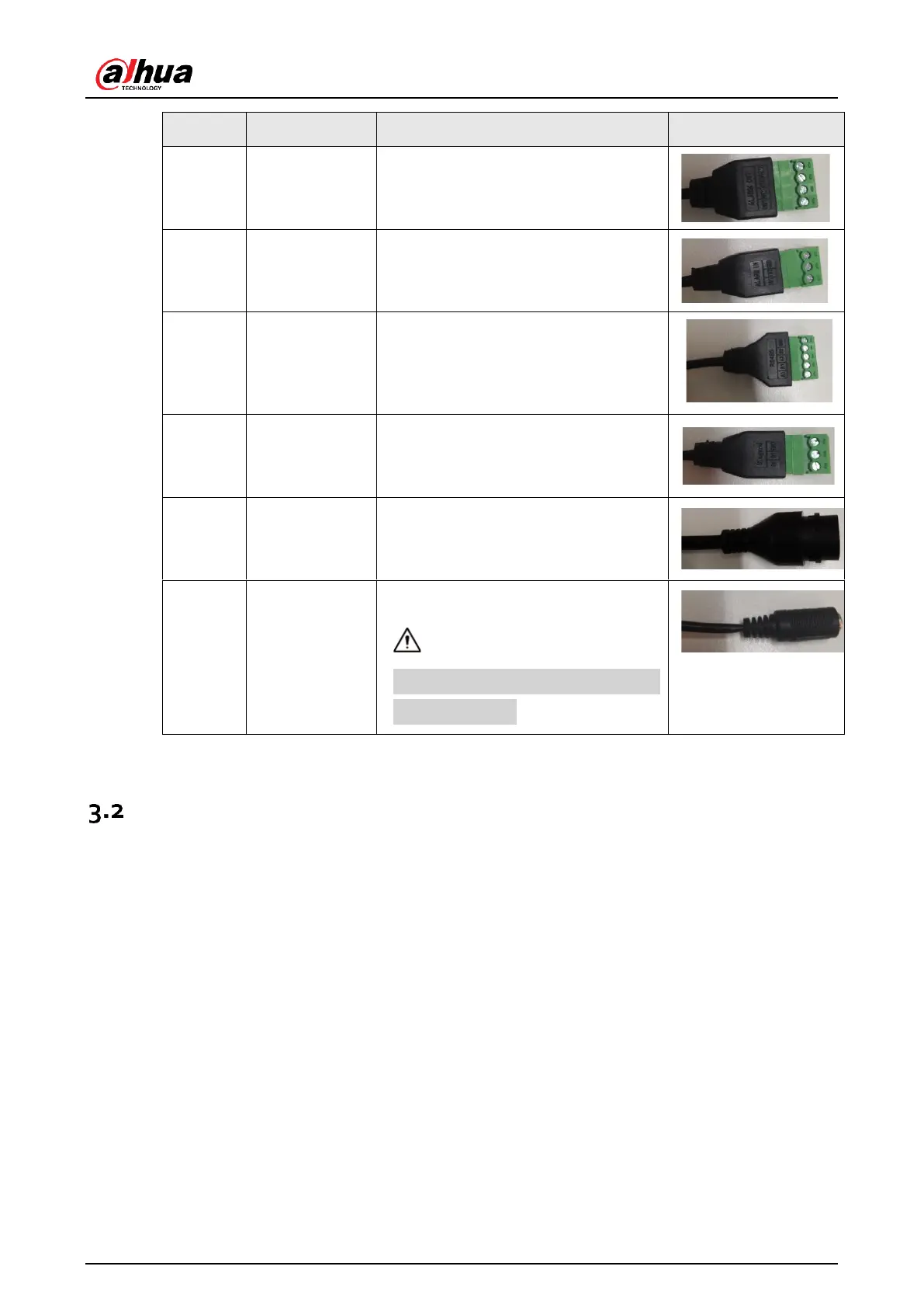
Connects and sends number plates to
access controller.
Connects to a network. It also supports
PoE power supply.
Connects to 12 VDC power supply.
Device damage will occur if power is not
supplied correctly.
Barrier Gate Wiring
For DHI-IPMECD-203X barrier gates, you can refer to Figure 3-2 for wiring of the arm opening control
cables. For DHI-IPMECD-203X barrier gate, to control the opening of the barrier gate, connect NO1
cable of the camera to OPEN port (port 10 on the terminal), and COM1 cable to GND port (port 12 on
the terminal) of the barrier gate motherboard. Connect the red cable of the anti-smashing radar to
DC12 V+ port (port 16 on the terminal); the black cable to OUT- port (port 17 on the terminal); the brown
cable to port 13 on the terminal; yellow cable to GND port (port 15 on the terminal) of the motherboard.
 Loading...