Configuring Alarm 12
5 Configuring Alarm
It has to cut off power first when connecting cables.
Alarm Input and Output Connection Description
Connect alarm input device to alarm input port of I/O cable. Step 1
Connect alarm output device to alarm output port of I/O cable. Alarm output is relay Step 2
switch output, and the alarm output port can only be connected to NO alarm device.
Open the web interface, select Setting > Event > Alarm.
Step 3
Make corresponding settings upon alarm input and output in the alarm setup interface, Step 4
and then click Save.
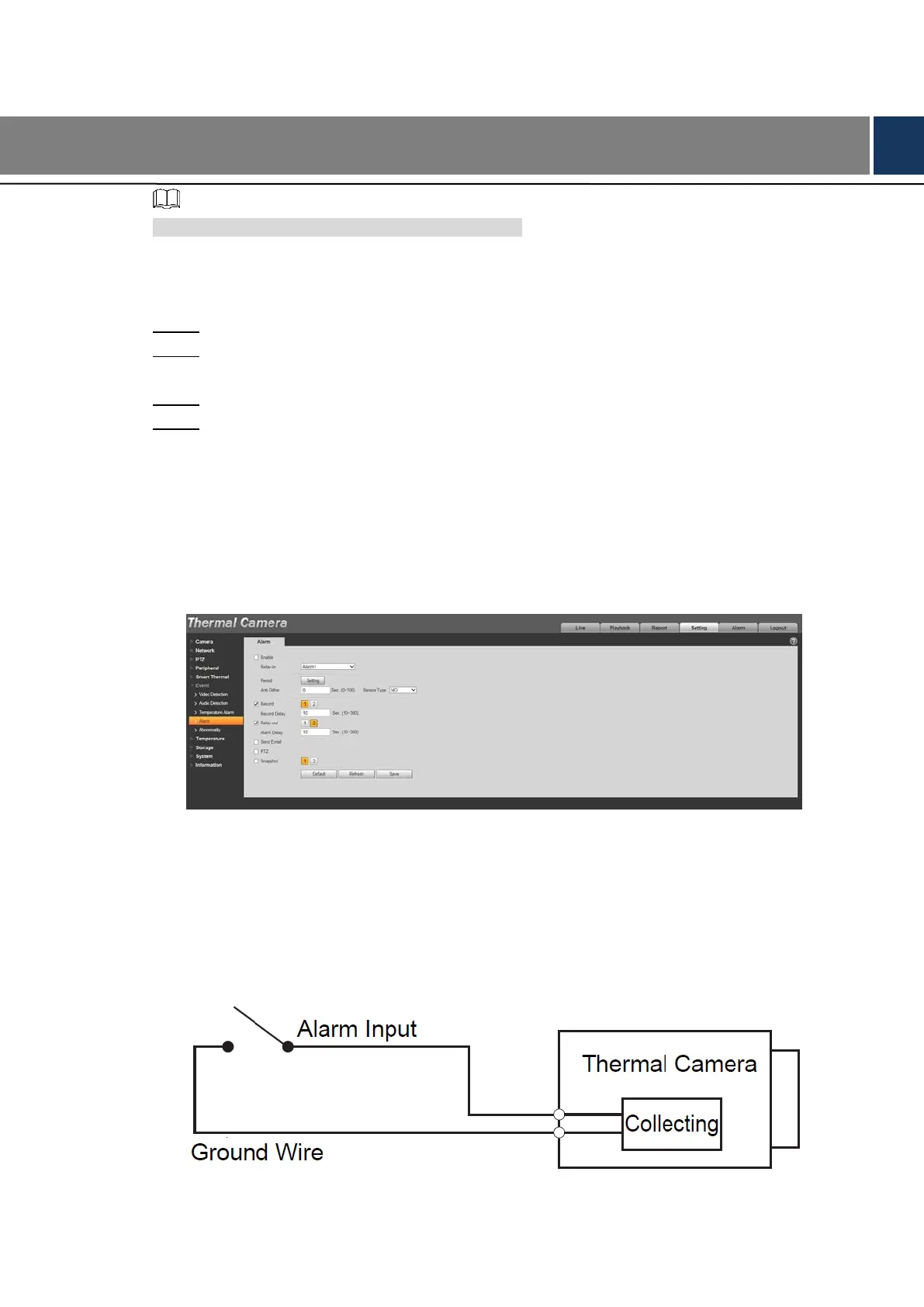
See Figure 5-1 for the Alarm interface.
Alarm input is corresponding to the alarm input port of device I/O cable. It is to set
corresponding NO and NC according to the high and low level signal generated by
alarm input device when alarm occurs.
Alarm output is corresponding to the alarm output port of device I/O cable.
The alarm interface Figure 5-1
Alarm Input and Output Figures
Alarm input: input signal is idle or grounded; the device can collect different states of alarm
input port. Input signal is connected to 3.3V or idle, device collects logic “1”; input signal is
grounded, the device collects logic “0”.
Alarm input Figure 5-2
 Loading...