7 Electrical installation
Installation manual
19
2MXM-A9, 3MXM-A9, 4MXM-A9, 5MXM-A9
R32 Split series
3P600450-9T – 2022.09
DANGER: RISK OF ELECTROCUTION
All electrical parts (including thermistors) are powered by
the power supply. Do NOT touch them with bare hands.
DANGER: RISK OF ELECTROCUTION
Disconnect the power supply for more than 10 minutes,
and measure the voltage at the terminals of main circuit
capacitors or electrical components before servicing. The
voltage MUST be less than 50VDC before you can touch
electrical components. For the location of the terminals,
see the wiring diagram.
AC
DC
DC
S20 S21 S22 S23
S92
S93
S40
S80
S70
U W
V
DC-
FU2
S90
S24
AL2 AL1
e
f
g
h
a
b
c
d
DC(-)
FU2
a AL1, AL2 - solenoid valve lead wire connector*
b S20~24 - electronic expansion valve coil lead wire
connector (room A, B, C, D, E)*
c S40 – thermal overload relay lead wire and high pressure
switch connector*
d Multimeter (DC voltage range)
e S90~93 – thermistor lead wire connector
f S70 - fan motor lead wire connector
g S80 - 4-way valve lead wire connector
h Compressor lead wire connector
*May differ depending on the model.
7.1 Specifications of standard wiring
components
NOTICE
We recommend using solid (single-core) wires. If stranded
wires are used, twist the conductor to consolidate the end
or twist the conductor to consolidate the end in
combination with the usage of a round crimp-style terminal
on the end of the conductor. Details are described in
"Guidelines when connecting the electrical wiring" in the
installer reference guide.
Component
Power supply
cable
Voltage 220~240V
Current See table below (A)
Phase 1~
Frequency 50Hz
Wire size MUST comply with national
wiring regulation.
3-core cable
Wire size based on the current,
but not less than 2.5mm
2
.
Component
Interconnection
cable
(indoor↔outdoo
r)
Voltage 220~240V
Wire size Only use harmonised wire
providing double insulation and
suitable for applicable voltage.
4-core cable
Minimum 1.5mm
2
Recommended circuit breaker See table below (B)
Earth leakage circuit breaker /
residual current circuit breaker
MUST comply with national
wiring regulation
Model A B
3MXM40 16.0A 16A
2MXM68 19.8A 20A
3MXM52 16.3A
3MXM68 19.8A
4MXM68 19.8A
4MXM80 20.4A 25A
5MXM90 25.9A 32A
Electrical equipment must comply with EN/IEC 61000-3-12, the
European/International Technical Standard setting the limits for
harmonic currents produced by equipment connected to public low-
voltage systems with input current >16 A and ≤75 A per phase.
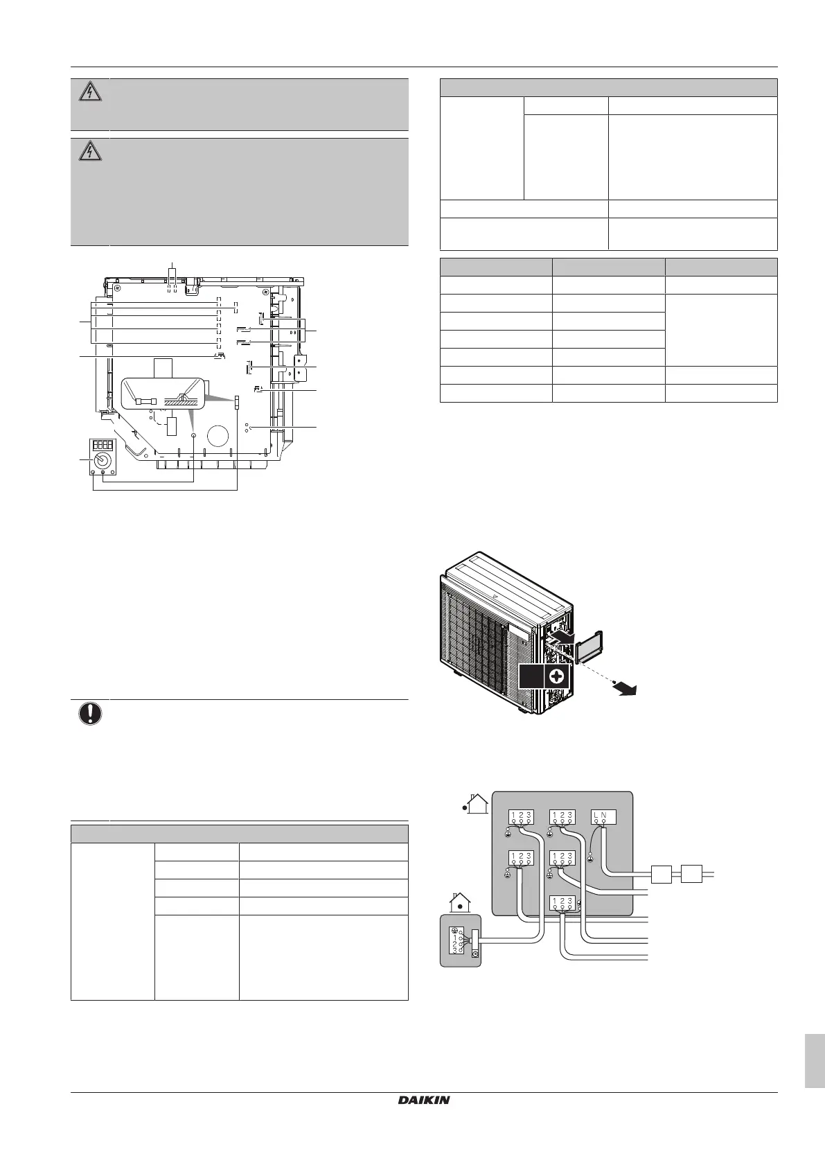
7.2 To connect the electrical wiring to
the outdoor unit
1 Remove the switch box cover (1 screw).
2 Connect the wires between the indoor and outdoor units so that
the terminal numbers match. Make sure to match the symbols
for piping and wiring.
3 Make sure to connect correct wiring to correct room.
e-B
e-E
e-C
e-D
a-A
e-A
a-C a-D
a-E
a-B
b c
d
a Terminal for room (A, B, C, D, E)*
b Circuit breaker
c Residual current device
d Power supply wire
e Interconnection wire for room (A, B, C, D, E)*
*May differ depending on the model.
 Loading...