11 Maintenance and service
Installation manual
23
2MXM-A9, 3MXM-A9, 4MXM-A9, 5MXM-A9
R32 Split series
3P600450-9T – 2022.09
▪ One or more LEDs are permanently on: abnormal stop (follow the
diagnosis procedure on the back of the right side plate and refer to
service manual).
10.3.2 To perform a test run
INFORMATION
If the unit runs into an error during commissioning, see the
service manual for the detailed troubleshooting guidelines.
Prerequisite: Power supply MUST be in the specified range.
Prerequisite: Test run operation may be done in cooling or heating
mode.
Prerequisite: Test run should be done in accordance with the
operation manual of the indoor unit to make sure that all functions
and parts are working properly.
1 In cooling mode, select the lowest programmable temperature.
In heating mode, select the highest programmable temperature.
2 Measure the temperature at the indoor unit inlet and outlet after
running the unit for about 20minutes. The difference should be
more than 8°C (cooling) or 20°C (heating).
3 First check operation of each unit individually, then check
simultaneous operation of all indoor units. Check both heating
and cooling operation.
4 When test run is finished, set the temperature to a normal level.
In cooling mode: 26~28°C, in heating mode: 20~24°C.
INFORMATION
▪ Test run can be disabled if necessary.
▪ After the unit is turned OFF, it cannot be started again
for 3 minutes.
▪ When the test run is started in the heat mode right after
turning the safety breaker on, in some cases no air will
be output for about 15 minutes in order to protect the
unit.
▪ Operate only air conditioner during test run. Do NOT
operate the Hybrid for Multi or the DHW generator
during test run.
▪ During cooling operation, frost may form on the gas
stop valve or other parts. This is normal.
INFORMATION
▪ Even if the unit is turned OFF, it consumes electricity.
▪ When the power turns back on after a power break, the
previously selected mode will be resumed.
10.4 Starting up the outdoor unit
See the indoor unit installation manual for configuration and
commissioning of the system.
11 Maintenance and service
NOTICE
General maintenance/inspection checklist. Next to the
maintenance instructions in this chapter, a general
maintenance/inspection checklist is also available on the
Daikin Business Portal (authentication required).
The general maintenance/inspection checklist is
complementary to the instructions in this chapter and can
be used as a guideline and reporting template during
maintenance.
NOTICE
Maintenance MUST be done by an authorised installer or
service agent.
We recommend performing maintenance at least once a
year. However, applicable legislation might require shorter
maintenance intervals.
NOTICE
Applicable legislation on fluorinated greenhouse gases
requires that the refrigerant charge of the unit is indicated
both in weight and CO
2
equivalent.
Formula to calculate the quantity in CO
2
equivalent
tonnes: GWP value of the refrigerant × total refrigerant
charge [in kg] / 1000
12 Disposal
NOTICE
Do NOT try to dismantle the system yourself: dismantling
of the system, treatment of the refrigerant, oil and other
parts MUST comply with applicable legislation. Units
MUST be treated at a specialised treatment facility for
reuse, recycling and recovery.
INFORMATION
To protect the environment, make sure to perform an
automatic pump down operation when relocating or
dismantling the unit. For the pump down procedure, refer
to the service manual or the installer reference guide.
13 Technical data
▪ A subset of the latest technical data is available on the regional
Daikin website (publicly accessible).
▪ The full set of latest technical data is available on the Daikin
Business Portal (authentication required).
13.1 Wiring diagram
The wiring diagram is delivered with the unit, located inside of
the outdoor unit (bottom side of the top plate).
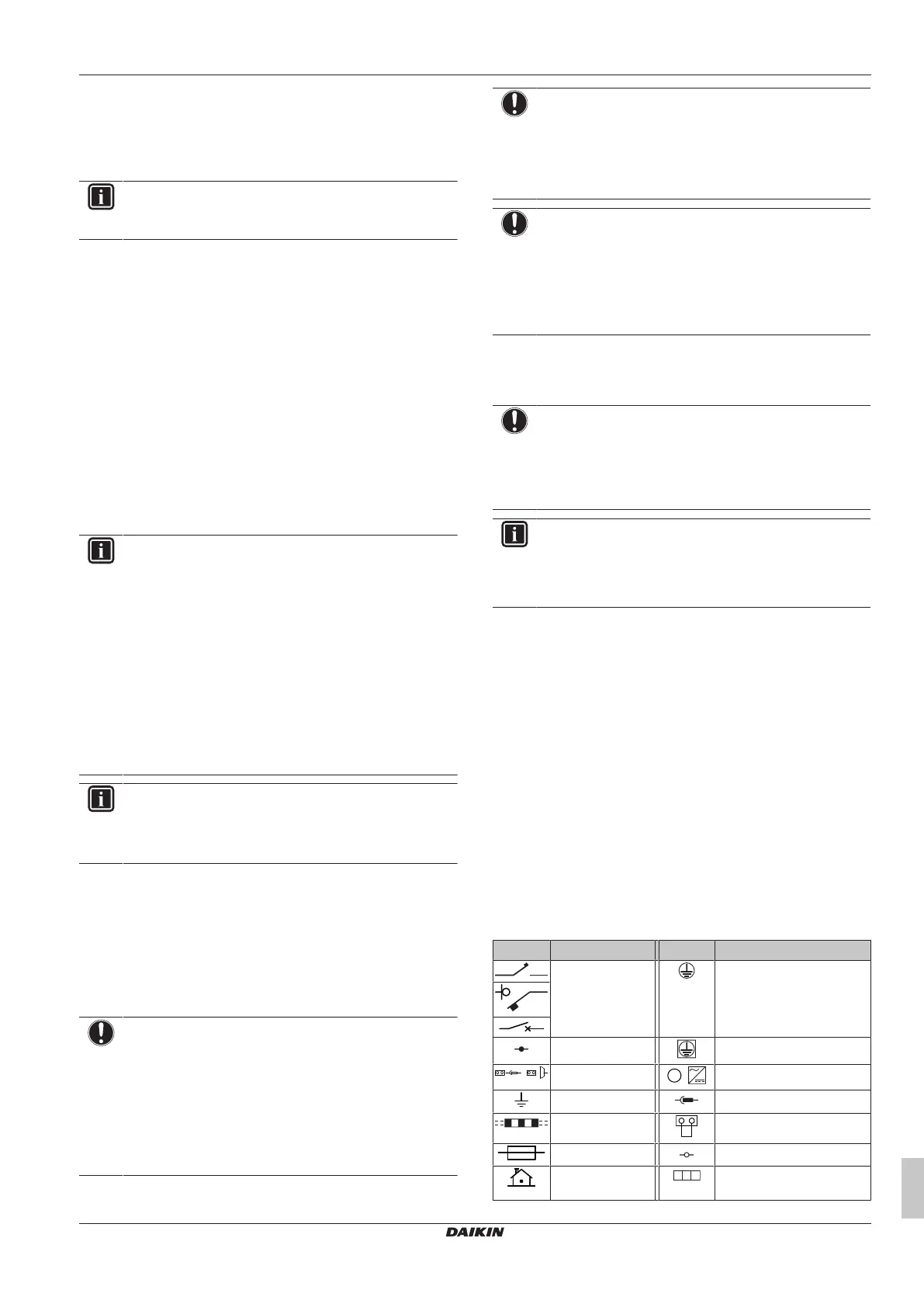
13.1.1 Unified wiring diagram legend
For applied parts and numbering, refer to the wiring diagram on the
unit. Part numbering is by Arabic numbers in ascending order for
each part and is represented in the overview below by "*" in the part
code.
Symbol Meaning Symbol Meaning
Circuit breaker Protective earth
Connection Protective earth (screw)
Connector
,
Rectifier
Earth Relay connector
Field wiring Short-circuit connector
Fuse Terminal
Indoor unit Terminal strip
 Loading...