Check SiUS121736EA
209 Service Diagnosis
8. Check
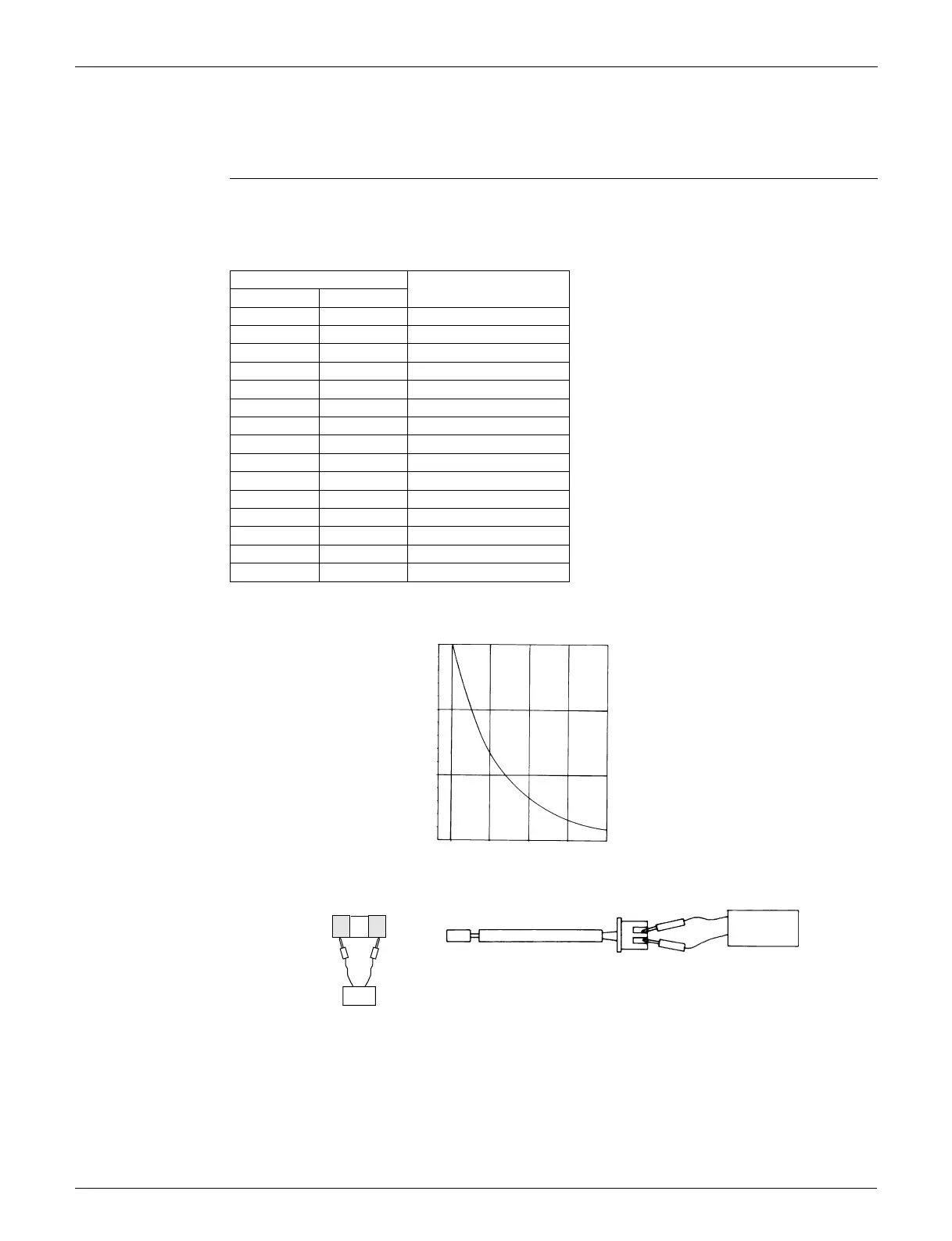
8.1 Thermistor Resistance Check
Check No.01 Disconnect the connectors of the thermistors from the PCB, and measure the resistance of each
thermistor using a multimeter.
The data is for reference purpose only.
When the room temperature thermistor is soldered on a PCB, remove the PCB from the control
PCB to measure the resistance.
When the connector of indoor heat exchanger thermistor is soldered on a PCB, remove the
thermistor and measure the resistance.
Thermistor temperature
Resistance (kΩ)
°C °F
–20 –4 197.8
–15 5 148.2
–10 14 112.1
–5 23 85.60
0 32 65.93
5 41 51.14
10 50 39.99
15 59 31.52
20 68 25.02
25 77 20.00
30 86 16.10
35 95 13.04
40 104 10.62
45 113 8.707
50 122 7.176
(R25°C (77°F) = 20 kΩ, B = 3950 K)
(kΩ)
150
100
50
–15 0 15 30 45
(R14467)
5 32 59 86 113
(˚C)
(˚F)
Multimeter
(R20505)
Room temperature
thermistor
Multimeter
Resistance range
Other thermistors
(R23371)
 Loading...