3 About the system
Operation manual
4
EHBH/X04+08EA/EJ6V+9W + EHVH/X04+08S(U)18+23EA/EJ3V
+6V+9W
Daikin Altherma 3 R F+W
4P629084-2 – 2020.08
WARNING
▪ Do NOT pierce or burn refrigerant cycle parts.
▪ Do NOT use cleaning materials or means to accelerate
the defrosting process other than those recommended
by the manufacturer.
▪ Be aware that the refrigerant inside the system is
odourless.
WARNING
Air purging heat emitters or collectors. Before you
purge air from heat emitters or collectors, check if or
is displayed on the home screen of the user interface.
▪ If not, you can purge air immediately.
▪ If yes, make sure that the room where you want to
purge air is sufficiently ventilated. Reason: Refrigerant
might leak into the water circuit, and subsequently into
the room when you purge air from the heat emitters or
collectors.
NOTICE
Do NOT try to dismantle the system yourself: dismantling
of the system, treatment of the refrigerant, oil and other
parts MUST comply with applicable legislation. Units
MUST be treated at a specialised treatment facility for
reuse, recycling and recovery.
3 About the system
Depending on the system layout, the system can:
▪ Heat up a space
▪ Cool down a space (if a heating/cooling heat pump model is
installed)
▪ Produce domestic hot water (if a DHWtank is installed)
3.1 Components in a typical system
layout
A Main zone. Example: Living room.
B Additional zone. Example: Bedroom.
C Technical room. Example: Garage.
a Outdoor unit heatpump
b Indoor unit heatpump
c Domestic hot water (DHW) tank
d User interface of the indoor unit
e User interface used as room thermostat
f Underfloor heating
g Radiators, heatpump convectors, or fancoil units
INFORMATION
The indoor unit and the domestic hot water tank (if
installed) can be separated or integrated depending on the
indoor unit type.
4 Operation
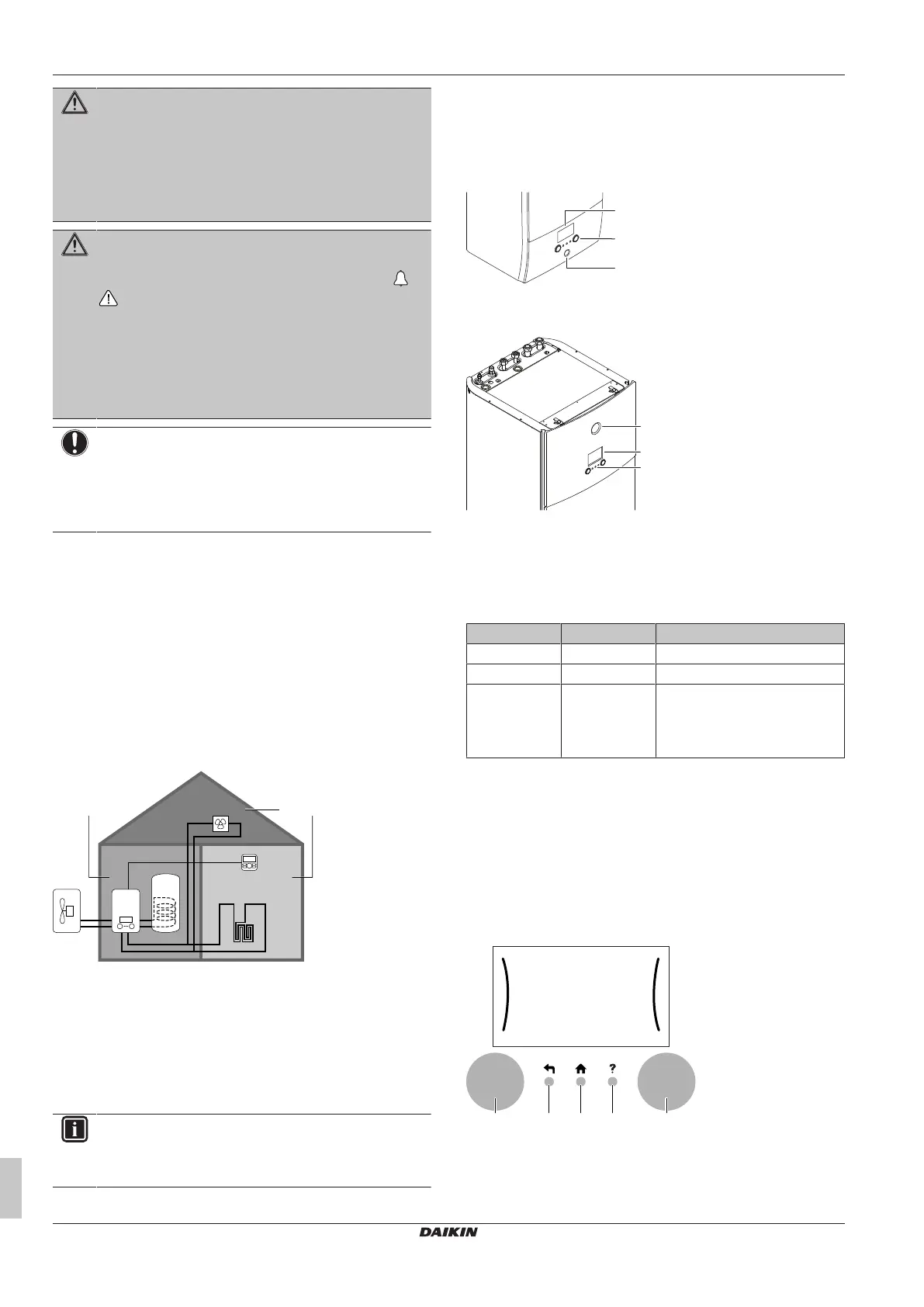
4.1 User interface: Overview
The user interface has the following components:
a Status indicator
b LCD screen
c Dials and buttons
a Status indicator
b LCD screen
c Dials and buttons
Status indicator
The LEDs of the status indicator light up or blink to show the
operating mode of the unit.
LED Mode Description
Blinking blue Standby The unit is not in operation.
Continuous blue Operation The unit is in operation.
Blinking red Malfunction A malfunction occurred.
See "7.1To display the help text
in case of a malfunction"[415]
for more information.
LCD screen
The LCD screen has a sleeping function. After 15 min of non-
interaction with the user interface, the screen darkens. Pressing any
button or rotating any dial awakens the display.
Dials and buttons
You use the dials and buttons:
▪ To navigate through the screens, menus and settings of the LCD
screen
▪ To set values
 Loading...