IM 916-5 • MICROTECH COMMUNICATION MODULE 6 www.DaikinApplied.com
The following section describes how to eld install a new
BACnet IP communication module or replace an existing
module on the unit controller.
This equipment contains sensitive electronic components that may be
damaged by electrostatic discharge from your hands. Before you handle
a communication module, you need to touch a grounded object, such as
the metal enclosure, in order to discharge the electrostatic potential from
your body.
.
This equipment must be properly grounded. Only personnel knowledgeable
in the operation of the equipment being controlled must perform connections
and service to the unit controller.
The BACnet communication module eld-installed kit ships
with the following items:
• The BACnet IP communication module
• Board-to-board connector (Figure 4)
Refer to the Parts section for replacement information.
Follow these steps to install a BACnet communication module
on the unit controller. The module can be connected directly to
the unit controller itself or to an existing module, if present.
There is a limit of three devices that can be attached
to the left side of the unit controller.
1. Set the “Control Mode = O” from the main menu on the
unit controller display menu. This must be done prior to
installing a new communication module.
2. Remove power from the unit controller.
3. Carefully remove the blue plastic knockout strip on
the far left end of the unit controller itself (or additional
module, if present). Figure 4 shows the knockout strip
after it has been removed from the unit controller.
4. To prevent damage to the unit controller, insert a small
screwdriver or other tool to the tab on the bottom of the
unit controller and pull the screwdriver away from the
controller.
5. Carefully remove the blue plastic knockout on the far
right side of the BACnet communication module.
6. Insert the board-to-board connector into the BACnet
communication module. Note that it only ts one way and
that the baes must line up with corresponding slots in
BACnet communication module and the unit controller
(Figure 3 and Figure 5).
7. Insert the other end of the board-to-board connector
to the far left side of the unit controller or other
communication module, if attached (Figure 1).
8. Insert a CAT 5 Ethernet cable into the communication
module’s network connector (Figure 2 shows the
location of network connector).
9. Power up the unit controller.
10. The unit controller automatically resets itself
approximately 30 seconds after it is powered up. This
reset is necessary so that the BACnet communication
module is synchronized with the unit controller.
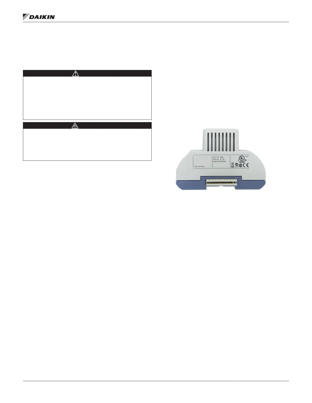
Figure 5: Communication Module with Board-to-Board
Connector Inserted
Follow these steps to remove and replace a BACnet
communication module. Note that it may already be connected
to either the unit controller or to an existing module.
1. Set the “Control Mode = O” from the main menu on the
unit controller display menu. This must be done prior to
replacing a communication module.
2. Remove power from the unit controller.
3. Locate the BACnet communication module to the left of
the unit controller (Figure 1).
4. Pull the network cable connector from the BACnet
communication module.
5. Grasp the BACnet communication module and gently
pull it from the unit controller (or from an adjacent
module, if it is attached to one).
6. Install the new BACnet communication module.
7. Insert a CAT 5 Ethernet cable into the communication
module’s network connector (Figure 2).
8. Apply power to the unit controller.
The unit controller automatically resets itself
approximately 30 seconds after power has been
applied to it. This reset is necessary so that the
BACnet communication module can synchronize with
the unit controller.
 Loading...