36
NETWORK TROUBLESHOOTING
The integrated furnace control has some on-board tools that
may be used to troubleshoot the network. These tools are: red
communications LED, green receive (Rx) LED, and learn but-
ton.
• Red communications LED – Indicates the status of
the network. The table below indicates the LED status
and the corresponding potential problem.
• Green receive LED – Indicates network traffic. The
table below indicates the LED status and the
corresponding potential problem.
• Learn button – Used to reset the network. Depress
the button for approximately 2 seconds to reset the
network.
SYSTEM TROUBLESHOOTING
NOTE: Refer to the instructions accompanying the CT
compatible outdoor AC/HP unit for troubleshooting information.
Refer to the Troubleshooting Chart in the back of this manual
for a listing of possible furnace error codes, possible causes
and corrective actions.
Submenu Item Indication (for Display Only; not User Modifiable)
Mode (MODE) Displays the current furnace operating mode
CFM (CFM) Displays the airflow for the current operating mode
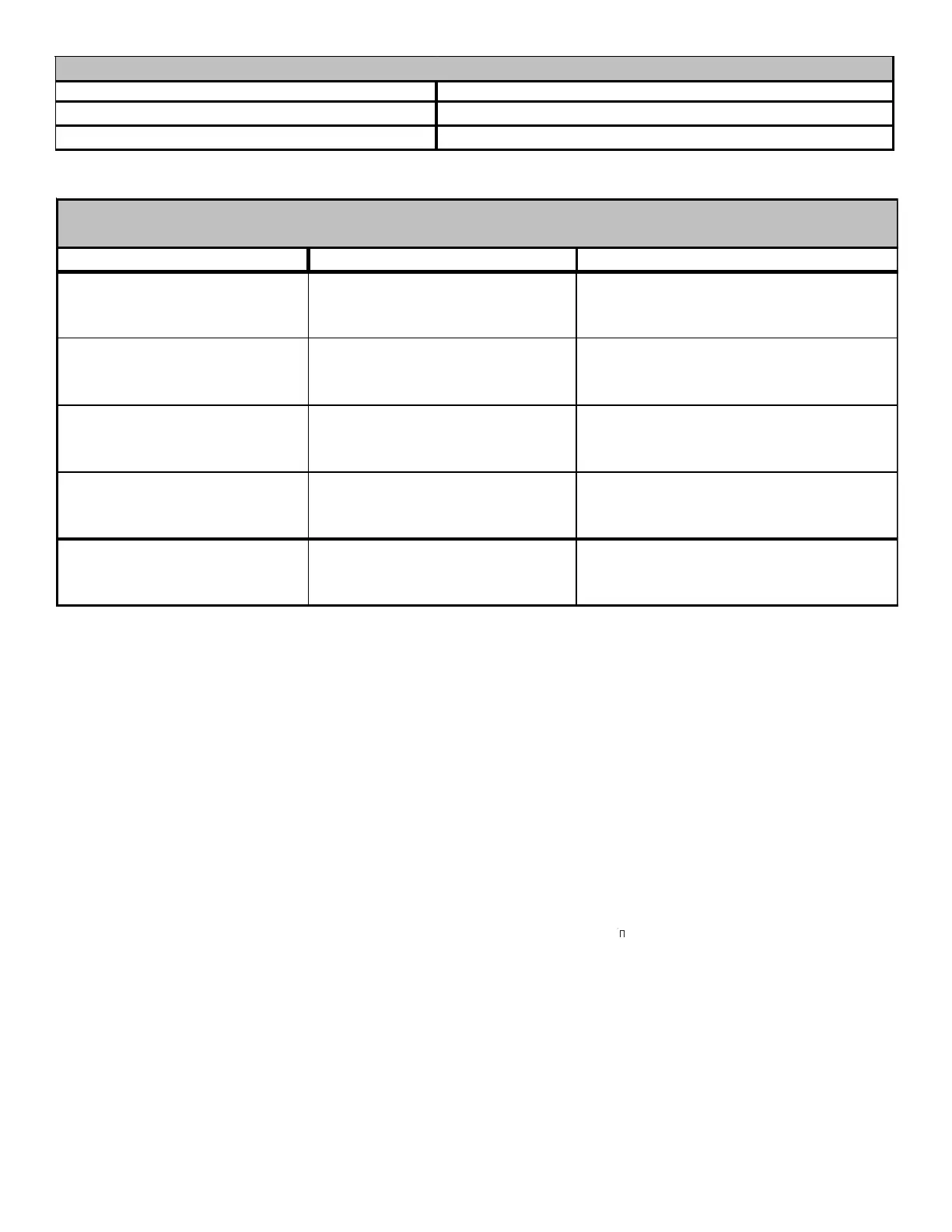
STATUS
Submenu Item User Modifiable Options Comments
Cool Airflow (CL CFM) 18, 24, 30, 36, 42, 48, or 60, default
is 18
Selects the airflow for the non-
communicating compatible single stage AC
unit
Cool Airflow Trim (CL TRM) -10% to +10% in 2% increments,
default is 0%
Selects the airflow trim amount for the non-
communicating compatible single stage AC
unit
Cool Airflow Profile (CL PRFL) A, B, C, or D, default is A Selects the airflow profile for the non-
communicating compatible single stage AC
unit
Cool ON Delay (CL ON) 5, 10, 20, or 30 seconds, default is
5 seconds
Selects the indoor blower ON delay for the
non-communicating compatible single
stage AC unit
Cool OFF Delay (CL OFF) 30, 60, 90, or 120 seconds, default
is 30 seconds
Selects the indoor blower OFF delay for the
non-communicating compatible single
stage AC unit
NON-COMM (APPLIES ONLY TO A COMMUNICATING COMPATIBLE FURNACE MATCHED
WITH A NON-COMMUNICATING COMPATIBLE SINGLE STAGE AIR CONDITIONER)
N
ORMAL
S
EQUENCE
OF
O
PERATION
POWER U P
The normal power up sequence is as follows:
• 115 VAC power applied to furnace.
• Integrated control module performs internal checks.
• Integrated control module displays 8
8 on dual 7-
segment display LED’s.
• Integrated control module monitors safety circuits
continuously.
• Furnace awaits call from thermostat. Dual 7-segment
LED’s display O while awaiting call from thermostat.
HEATING MODE
The normal operational sequence in heating mode is as fol-
lows:
• R and W1 (or R and W1/W2) thermostat contacts close,
initiating a call for heat.
• Integrated control module performs safety circuit checks.
• Induced draft blower is energized on high speed for a 15-
second prepurge. Humidifier terminal is energized with
induced draft blower.
 Loading...


