25 | Technical data
Installer and user reference guide
137
RXYTQ
VRV IV+ heat pump for high ambient temperatures
4P561157-1B – 2021.11
f Accumulator q Electrical component box
g Expansion valve, main (Y1E) r Service port, refrigerant charge
h Expansion valve, subcool heat
exchanger (Y2E)
s Stop valve, liquid
i Expansion valve, storage vessel
(Y4E)
t Stop valve, gas
j Subcool heat exchanger u Expansion valve, liquid cooling
(Y3E)
k Oil separator v Service port
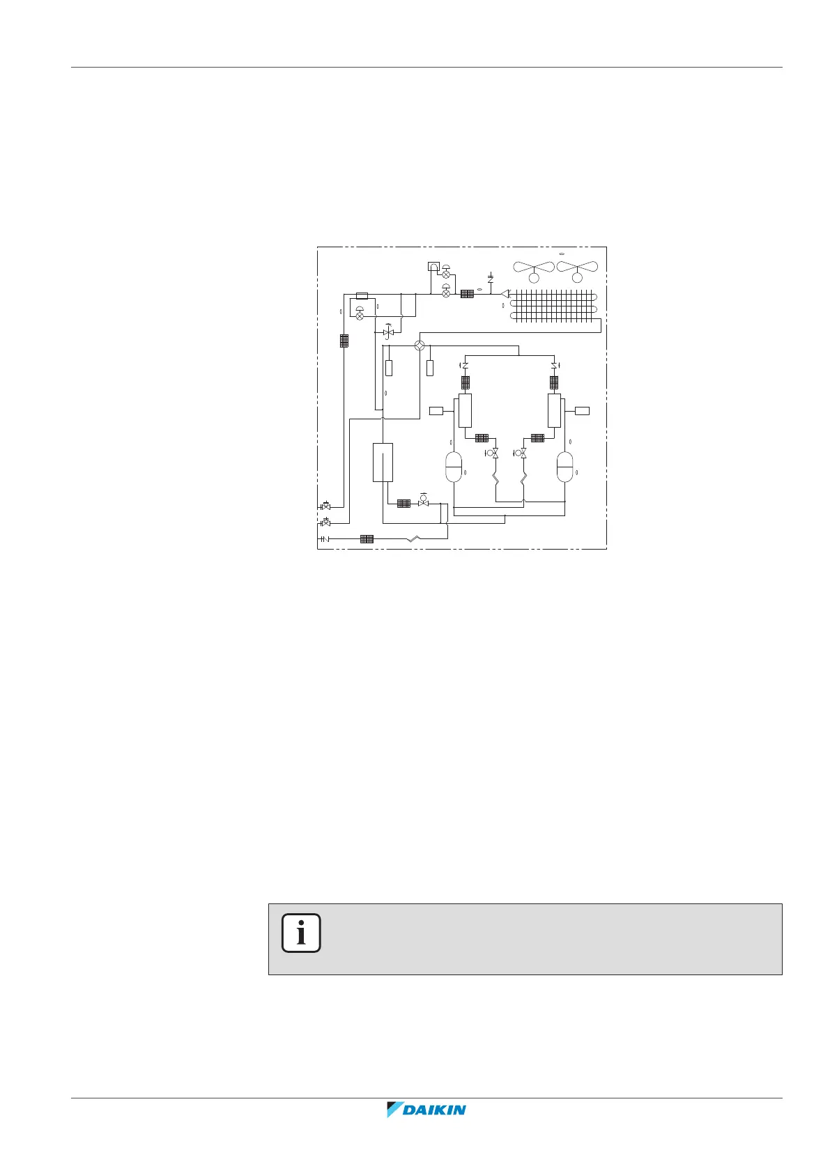
Piping diagram: RXYTQ14+16
a
b
k k
nm
f
l
j
o
t
s
h
c
e
d d
e
M
sv
sv
INV INV
sv
M1C
M2C
M1F
M
M2F
(S1NPH)
(S1NPL)
(S1PH) (S2PH)
HPS
R6T
R5T
R1T
R9TR8T
R21T
R22T
R3T
HPS
r
R4T
g
u
v
a Compressor (M1C) l Solenoid valve, oil accumulator
(Y2S)
b Compressor (M2C) m Solenoid valve, oil1 (Y3S)
c Heat exchanger n Solenoid valve, oil2 (Y4S)
d Fan o 4‑way valve, main (Y1S)
e Fan motor (M1F, M2F) p 4‑way valve, sub (Y5S)
f Accumulator q Electrical component box
g Expansion valve, main (Y1E) r Service port, refrigerant charge
h Expansion valve, subcool heat
exchanger (Y2E)
s Stop valve, liquid
i Expansion valve, storage vessel
(Y4E)
t Stop valve, gas
j Subcool heat exchanger u Expansion valve, liquid cooling
(Y3E)
k Oil separator v Service port
25.3 Wiring diagram: Outdoor unit
Refer to the wiring diagram sticker on the unit. The abbreviations used are listed
below:
INFORMATION
The wiring diagram on the outdoor unit is only for the outdoor unit. For the indoor
unit or optional electrical components, refer to the wiring diagram of the indoor unit.
1 This wiring diagram applies only to the outdoor unit.
2 Symbols (see below).
3 When using the optional adapter, refer to the installation manual of the
optional adapter
 Loading...