18 | Electrical installation
Installer and user reference guide
93
RXYTQ
VRV IV+ heat pump for high ambient temperatures
4P561157-1B – 2021.11
Field piping can be routed from front or bottom of the unit (going left or right).
Refer to "17.2.4To route the refrigerant piping"[471].
▪ Be sure to follow the limits below. If the unit-to-unit cables are beyond these
limits, it may result in malfunction of transmission:
- Maximum wiring length: 1000m.
- Total wiring length: 2000m.
- Maximum inter unit wiring length between outdoor units: 30m.
- Transmission wiring to cool/heat selector: 500m.
- Maximum number of branches: 16.
▪ Maximum number of independent interconnectable systems: 10.
▪ Up to 16 branches are possible for unit-to-unit cabling. No branching is allowed
after branching (see figure below).
For the above wiring, always use vinyl cords with 0.75 to 1.25mm
2
sheath or cables
(2-core wires). (3-core wire cables are allowable for the cooler/heater changeover
user interface only.)
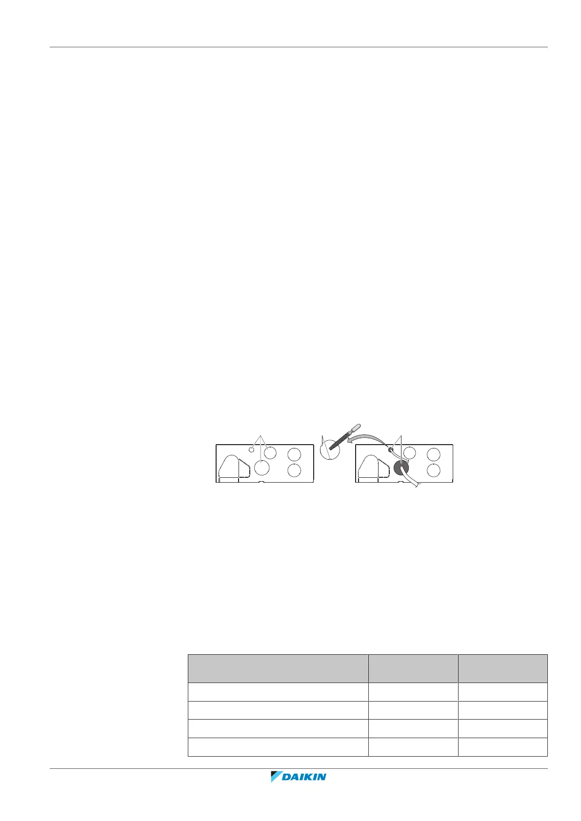
18.1.4 Guidelines when knocking out knockout holes
▪ To punch a knockout hole, hit on it with a hammer.
▪ After knocking out the holes, we recommend removing any burrs and paint the
edges and areas around the holes using repair paint to prevent rusting.
▪ When passing electrical wiring through the knockout holes. prevent damage to
the wires by wrapping the wiring with protective tape, putting the wires through
field supplied protective wire conduits at that location, or install suitable field
supplied wire nipples or rubber bushings into the knockout holes.
a Knockout hole
b Burr
c Remove burrs
d If there are any possibilities that small animals enter the system through the
knockout holes, close the holes with packing materials (to be prepared on-site)
18.1.5 Safety device requirements
The power supply must be protected with the required safety devices, i.e. a main
switch, a slow blow fuse on each phase and an earth leakage protector in
accordance with the applicable legislation.
Selection and sizing of the wiring should be done in accordance with the applicable
legislation based on the information mentioned in the table below.
Model Minimum circuit
ampacity
Recommended
fuses
RXYTQ8 16.1A 20A
RXYTQ10 22.0A 25A
RXYTQ12 24.0A 32A
RXYTQ14 27.0A 32A
 Loading...