Installation and operation manual
6
RWEYQ8+10T7Y1B
VRV-W IV System Air Conditioner
4P347465-1A – 2013.04
5. Overview of unit
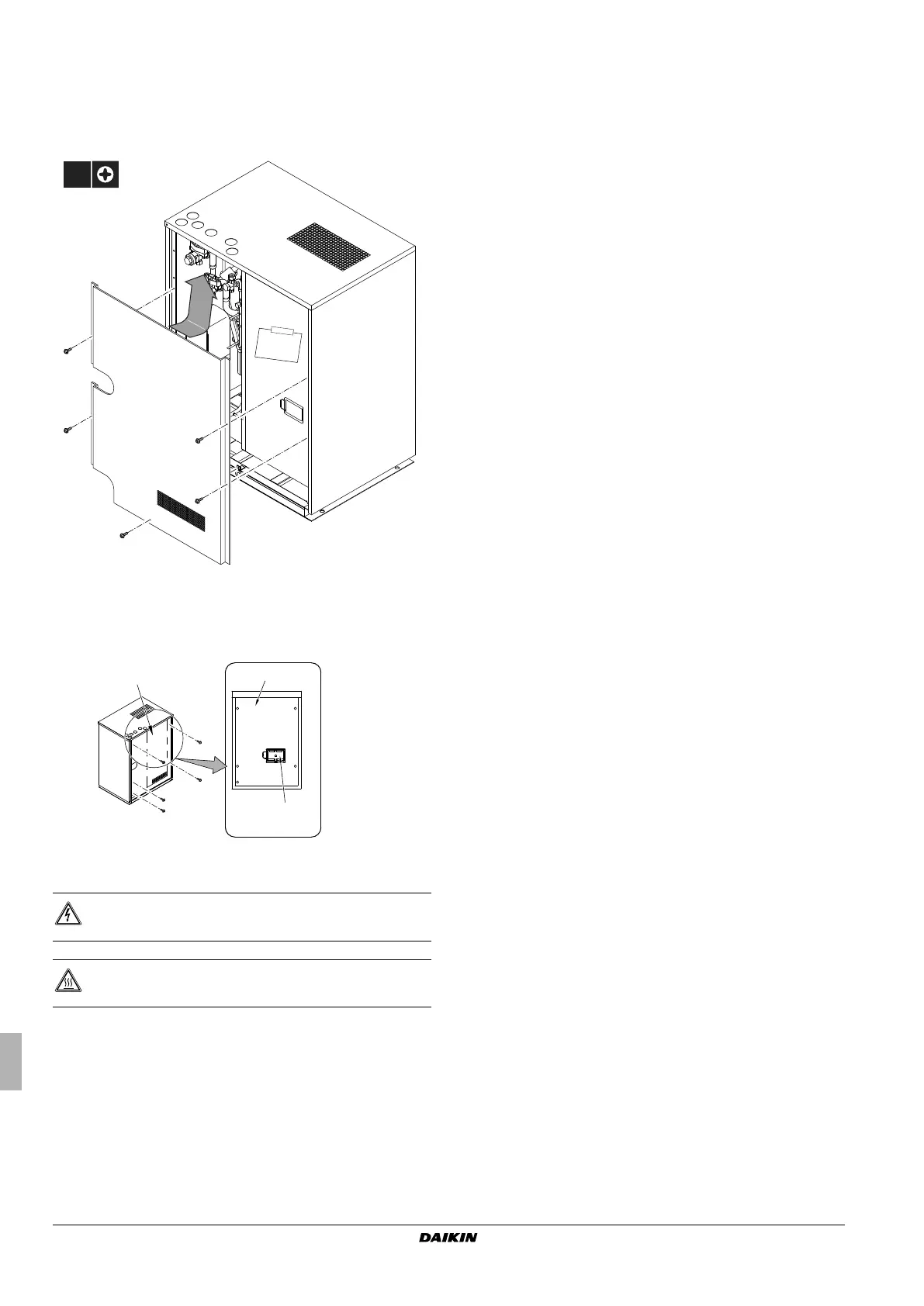
5.1. Opening the unit
To gain access to the unit, the front plate needs to be opened as
follows:
1 Location of manual
2 Location of accessory pipes
3 Location of water filter
Once the front plate is open, the electrical component box can be
accessed by removing the electrical component box cover as follows.
1 Electrical component box
2 Cover of electrical component box
3 Inspection cover
5.2. Main components in the unit
For all the models a piping diagram and outlook drawing are
available. Depending on the model type some components in the
main component list may not be existing in the unit.
Main components: see figure 1, figure 2, and figure 3
1 Compressor (INV)
2 Plate heat exchanger
3 Receiver
4 Oil separator
5 Electronic expansion valve (main) (Y1E)
6 Electronic expansion valve (sub cool) (Y3E)
7 Solenoid valve (4-way valve) (main) (Y5S)
8 Solenoid valve (4-way valve) (sub) (Y7S)
9 Solenoid valve (hot gas) (Y1S)
10 Solenoid valve (oil recovery) (Y2S)
11 Solenoid valve (receiver gas intake) (Y3S)
12 Solenoid valve (receiver gas purge) (Y4S)
13 Solenoid valve (liquid pipe) (Y6S)
14 Electrical component box
15 Pressure switch (high) (S1PH)
16 Pressure sensor (high) (S1NPH)
17 Pressure sensor (low) (S1NPL)
18 Service port
19 HP/LP gas stop valve
20 Suction gas stop valve
21 Liquid stop valve
5.2.1 Piping diagram
See figure 3.
5.2.2 Outlook drawing
See figure 1 + figure 2.
DANGER: Electrical shock
See "2. General safety precautions" on page 2.
DANGER: Do not touch piping and internal parts.
See "2. General safety precautions" on page 2.
4P347465-1A.book Page 6 Monday, August 5, 2013 2:26 PM

 Loading...