RWEYQ8+10T7Y1B
VRV-W IV System Air Conditioner
4P347465-1A – 2013.04
Installation and operation manual
13
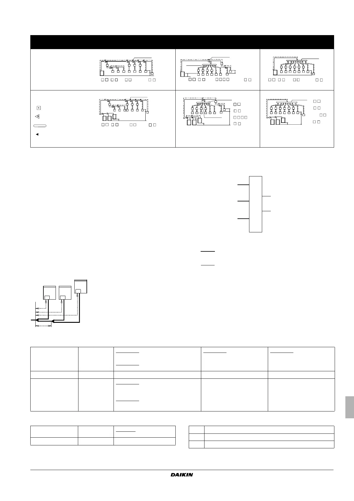
9.6. System containing VRV DX indoor units
System setup
Example of connection in case of heat recovery system
Connection to BS unit
Piping between outdoor unit and BS unit: thick line (3 pipe)
Piping between BS unit and indoor unit: thin line (2 pipe)
Example 3: with multi outdoor unit layout
Maximum allowable length
Between outdoor and indoor units
Between outdoor branch and outdoor unit (only in case >10 HP) Maximum allowable height difference
Branch with Refnet joint
Branch with Refnet joint and
Refnet header
Branch with Refnet header
Single outdoor unit
system
Example 1.1
Example 1.2 Example 1.3
Multi outdoor unit
system
Example 2.1 Example 2.2
Example 2.3
Indoor unit
Refnet joint
Refnet header
Multi outdoor unit
connection piping
kit
REFNET joint (A-G)
BS units
( B1 - B4 )
( 1 - 8 )
( 1 - 6 )
Cooling only
( 7
·
8 )
l
f
g
h
H2
H1
1234567
8
B2
B3 B4
B1
A
B
CDE
F
G
REFNET joint (A·B)
BS units ( B1 - B5 )
( 1 - 8 )
H1
1
23456
7
8
B1 B2 B3 B4
B5
d
e
f
g
h
i
j
k
l
m
a
b
Heat recovery system
( 1 - 4 , 7 · 8 )
Cooling only
( 5
·
6 )
a
b
f
h
j
d
c
e
g
ik
l
m
n
o
Unit
12
34567
8
B1 B2 B3 B4 B5 B6
BS units
( B1 - B6 )
( 1 - 8 )
( 1 - 6 )
Cooling only
( 7
·
8 )
REFNET joint (A-G)
( B1 - B4 )
( 1 - 8 )
system ( 1 - 6 )
Cooling only
( 7
·
8 )
a
b
c
d
e
1234567
8
First outdoor
branch
s
r
p
q
n
o
k
i
l
j
h
g
f
H3
H1
H2
m
B1 B2 B3 B4
ABCDE
FG
am
b
Unit 1
REFNET joint (A·B)
REFNET header
BS units
( B1 - B5 )
Heat recovery system
( 1 - 4 , 7 · 8 )
Indoor units
( 1 - 8 )
Cooling only
( 5
·
6 )
1
2
3
456
7
8
B1
B2 B3 B4
B5
c
d
e
f
g
h
i
j
k
l
n
p
o
u
t
s
r
H3
a
b
d
f
c
e
g
Unit 1
12
3
456 7
8
B6B5B4B3B2B1
BS units
( B1 - B6 )
Heat recovery
system ( 1 - 6 )
Indoor units
( 1 - 8 )
Cooling only
( 7
·
8 )
h
i
j
k
l
m
n
o
H3
Refnet joint Refnet joint
BS units BS units
Indoor units Indoor units
Heat recovery system Heat recovery system
Cooling only Cooling only
Refnet header Refnet header
First outdoor branch First outdoor branch
3-pipe 2-pipe
Outdoor
unit side
HP/LP gas Indoor
unit side
Suction
gas
Gas piping
Liquid
Liquid
piping
BS unit
Actual piping length 120 m Example 1.1
unit 8: a+b+c+d+e+s≤120 m
Example 2.1
unit 8: a+b+c+d+e+s≤120 m
Example 1.2
unit 4: a+b+i+j≤120 m
unit 5: a+b+k≤120 m
unit 8: a+m+n+p≤120 m
Example 1.3
unit 8: a+o≤120 m
unit 4: a+h+i≤120 m
Equivalent length
(2)
140 m ———
Total piping length 300 m Example 1.1
a+b+c+d+e+f+g+h+i+j+k+l+m+n+o+p+q+r+s
≤
300 m
Example 2.1
a+b+c+d+e+f+g+h+i+j+k+l+m+n+o+p+q+r+s
≤300 m
——
Actual piping length 10 m Example 3
r, s, t≤10 m; u≤5m
Equivalent length 13 m —
H1
≤
50 m (40 m) (if outdoor is located below indoor units)
H2
≤
15 m
H3
≤
2m
4P347465-1A.book Page 13 Monday, August 5, 2013 2:26 PM

 Loading...