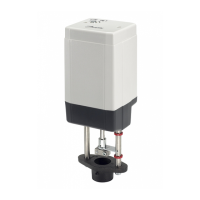
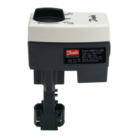
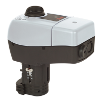
Adjustments AME210, AME213
40
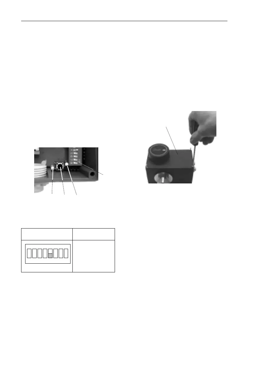
7.5 Setting the End Positions
After having completed the stroke
settings (see section 6), the end
positions “Valve open“ and “Valve
closed“ must be aligned with the
current and voltage values 0(4) -
20 mA, 0(2) - 10 V.
1. Switch on voltage supply.
➻
➻➻
➻ Green LED 1 must flash.
Red LED
2 may flash or be de-
activated.
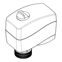
2. Set switch
S2:
3. Briefly press push-button
3.
➻
➻➻
➻ The actuator is opened and
closed several times; this
automatically aligns the end
positions.
During the alignment, the red
LED
2 is flashing, in the end it
will be deactivated.
The adjustments are
completed, the electrical ac-
tuator is in automatic
operation.
4. Re-mount cover
4 and tighten
Philips screws.
S2
Automatic
operation
1 2
S2
3
1 2 3 4 5 6 7 8
ON
4
 Loading...