46 | 180R9346 | AQ240486503020en-001702 © Danfoss | 2023.03
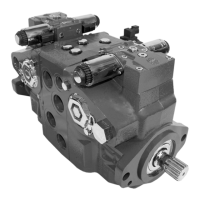
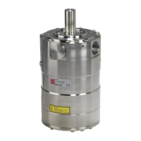
Operation guide Installation, Operation and Maintenance APP 53-92 pumps
3. Building up the
pump unit with BoWex
coupling
2.3 Preferred RO system design with ERD
For P&ID of a setup with an iSave, please see the
iSave® Data sheet 521B1378
2.4 Preferred RO system design with pumps
and ERDs in parallel
For systems with Danfoss pumps and ERDs in
parallel, please see our publication 180R9354,
Guideline for Parallel-coupled pumps and ERD.
2.5 Reversible pumps
If exposed to high-pressure in the outlet while
the electric motor is not energized, the pumps
may start spinning backwards. This will not harm
the pumps as long as the pressure in the inlet
does not exceed the max. pressure peak of
10 barg(145 psig).
If a non-return valve is mounted in the inlet line,
a low-pressure relief valve is required as protec-
tion against high-pressure pulses and high-pres-
sure in general.
Alternatively a high-pressure check valve can be
mounted in the pump discharge line to prevent
the pump from reversing.
The setup of “open-end system” ensures that the
inlet pressure does not exceed 10 barg (145 psig),
when a non-
return valve is mounted in the inlet.
2.6 General comments
A good ltration is vital to ensure a long and
trouble-free life of the pump.
As water has very low viscosity, the APP pumps
have been designed with very narrow clearance
in order to control internal leakage rates and
improve component performance. Therefore it is
important that the inlet water is ltered properly
to minimize the wear of the pump.
The main lter must have a ltration eciency of
99.98% at 10 m. We recommend to use
precision depth lter cartridges rated 10 m abs.
β10 ≥ 5000 (equivalent to a ltration eciency of
99.98%). Bag lters and string wounded lter
cartridges typically have only 50% ltration
eciency. This means that for each 100,000
particles reaching the lter, 50,000 particles pass
through it compared to only 20 particles in a
lter with an eciency of 99.98%.
For more information on the importance of
proper ltration, please see our data sheet
521B1009 on “Filtration”, which also will provide
you with an explanation of ltration denitions
and a guidance on how to select the right lter.
Monitoring
It is recommended to continuously monitor the
following conditions:
• Filter clogging
• Pressure (inlet- and outlet side of the pump)
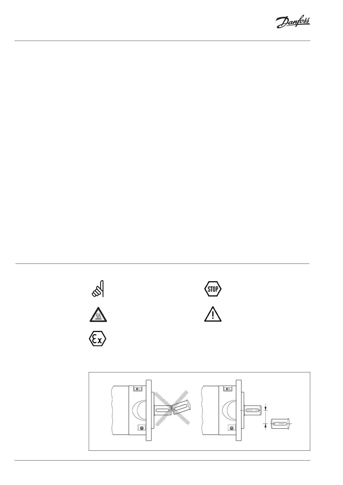
3.1 Assembly of the coupling
With the assembly please make sure
that the spline of the hub is fully co-
vered by the internal spline of elasto-
mer (please observe mounting dimen-
sions L
coupling
). Disregarding this advice
may cause damage to the coupling.
We recommend to inspect bores, shaft,
keyway and feather key for dimensional
accuracy before assembly.
Heating the hubs lightly (approx. 80 °C)
allows for an easier mounting on the
shaft.
Please pay attention to the ignition risk
in potentially explosive atmospheres!
Touching the heated hubs causes
burns.
Please wear safety gloves.
3.2 Alignment between the motor and
pump shaft
max. 0.5 mm
max. 0.02 inch
 Loading...