5.3 Connection brine
5.3.1 Connection brine DHP-H, DHP-H Opti, DHP-H Opti Pro, DHP-L, DHP-L Opti, DHP-L Opti Pro
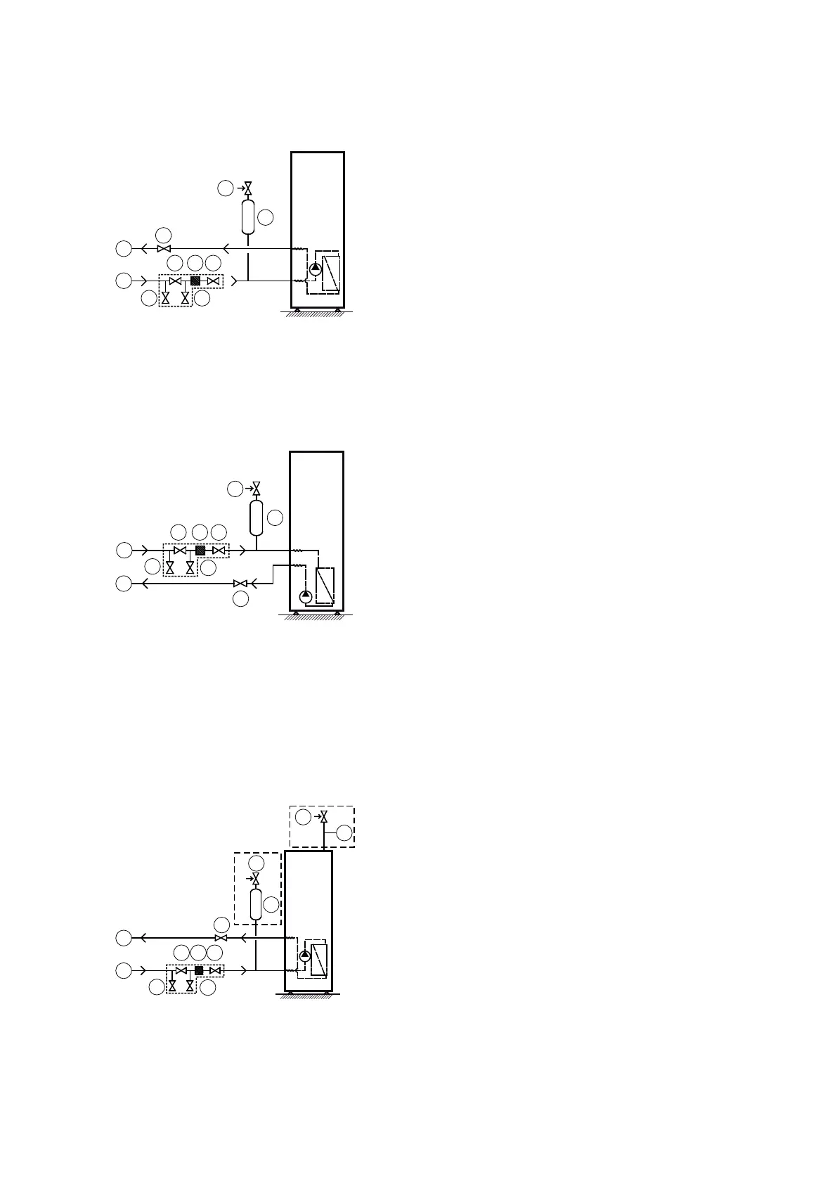
Figure 27. General connection diagram brine lines
Symbol explanation
1 Brine in
2 Brine out
3 Shut-off valve (part of the filler cock)
4 Dirt valve
5 Safety valve (1.5 bar)
6 Bleed and expansion tank
7 Shut-off valve
5.3.2 Connection brine DHP-C
Figure 28. General connection diagram brine lines
Symbol explanation
1 Brine in
2 Brine out
3 Shut-off valve (part of the filler cock)
4 Strainer
5 Safety valve (1.5 bar)
6 Bleed and expansion tank
7 Shut-off valve
5.3.3 Connection brine DHP-A, DHP-A Opti
If the outdoor unit is installed higher than the heat pump a pressure tank with safety valve must be connected to
the outlet for bleeding.
If the outdoor unit is installed at the same level or lower than the heat pump, the accompanying plastic vessel can
be used. The upper part of the outdoor unit must then not exceed the fluid level in the vessel.
Figure 29. General connection diagram, brine
lines
Symbol explanation
1 Brine in
2 Brine out
3 Shut-off valve (part of the filler cock)
4 Strainer
5 Safety valve (1.5 bar)
6 Bleed and expansion tank
7 Shut-off valve
8 Pressure tank
Installation instructions VMBMA1002 – 33
 Loading...