5.3.3.1 Connection brine Outdoor unit DHP-A, DHP-A Opti
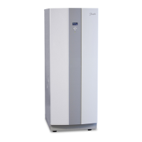
Figure 30. General connection diagram, brine lines
Symbol explanation
1 Brine out
2 Brine in
3 Flexible hoses
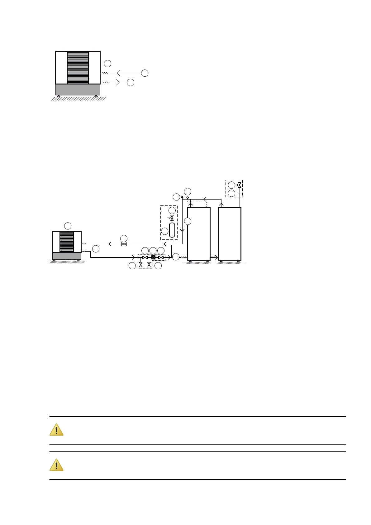
5.3.4 Connecting brine DHP-AL, DHP-AL Opti
If the outdoor unit is installed higher than the heat pump a pressure tank with safety valve must be connected to
the outlet for bleeding.
If the outdoor unit is installed at the same level or lower than the heat pump, the accompanying plastic vessel can
be used. The upper part of the outdoor unit must then not exceed the fluid level in the vessel.
Figure 31. General connection diagram, brine lines
Symbol explanation
1 Brine in
2 Brine out
3 Shut-off valve (part of the filler cock)
4 Strainer (part of the filler cock)
5 Safety valve (1.5 bar)
6 Bleed and expansion tank
7 Shut-off valve
8 Pressure tank
9 Outdoor unit
10 Flexible hoses
11 Bleed valve
12 Moved out supply line sensor, brine
5.3.5 Drilling holes for brine pipes
Caution! Ensure that the holes for the insert pipes are positioned so that there is room for the other
installations.
Caution! The brine pipes shall have separate lead-ins. If the wall lead-ins are below the highest ground
water level watertight lead-ins must be used.
34 – Installation instructions VMBMA1002
 Loading...