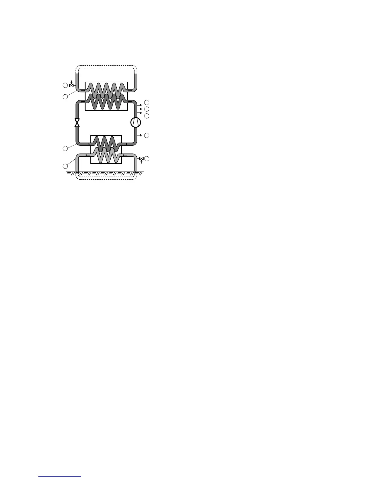
Figure 1. Check and safety functions
Symbol explanation
1 Heat transfer fluid circuit
2 Safety valve, heat transfer fluid circuit, externally
mounted
3 Refrigerant circuit
4 Operating pressure switch, normal
5 Operating pressure switch, alternative (only on cer-
tain heat pumps)
6 High pressure switch
7 Low pressure switch
8 Brine circuit
9 Safety valve, brine fluid circuit, externally mounted
Heat transfer fluid circuit (1)
If the pressure in this circuit exceeds the opening pressure for the safety valve (2), the valve opens, releases the
overpressure and closes again. The safety valve overflow pipe must have an open connection to the drain and
visibly flow into this in a frost-free environment.
Refrigerant circuit (3)
The refrigerant circuit's high pressure side is equipped with a high pressure switch (6) and one or two operating
pressure switches (4, 5), only one of which is connected. The connected operating pressure switch stops the com-
pressor when the working pressure is reached, which is when sufficient heat energy has been produced.
If the operating pressure switch does not work and the pressure continues to increase in the circuit, the high pres-
sure switch activates when its break pressure is reached, whereupon the compressor stops and the heat pump's
normal operation is blocked.
If the high pressure switch is activated an alarm indicator flashes on the heat pump's control panel and a warning
text appears in the display of the control panel. The blocked heat pump is reset by setting the operating mode to
OFF and then back to the previously selected mode.
The low pressure switch (7) stops the compressor and blocks the heat pump's operation if the pressure becomes
too low in the cooling circuit's low pressure side.
If the low pressure switch is activated, the heat pump's normal operation is blocked, an alarm indicator on the heat
pump's control panel flashes and a warning text appears in the display of the control panel. The blocked heat
pump is reset by setting the operating mode to OFF and then back to the previously selected mode.
Brine circuit (8)
If the pressure in this circuit exceeds the opening pressure for the safety valve (9), the valve opens, releases the
overpressure and closes again. The safety valve overflow pipe must have an open connection to the drain and
visibly flow into this in a frost-free environment.
Compressor
The compressor is equipped with a thermal over current relay to protect it against over current.
8 – Service instructions VMGFC302
 Loading...